


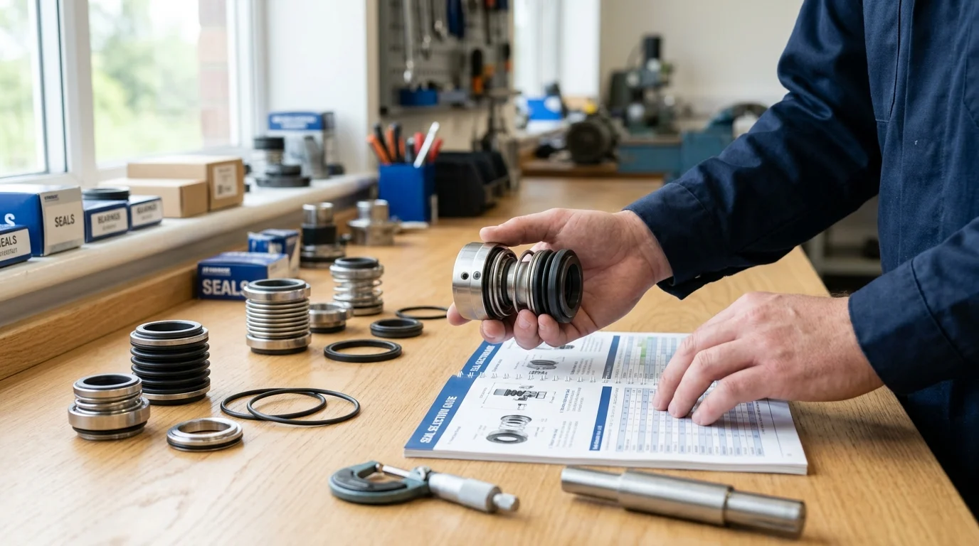
Why Proper Seal Selection Matters
Industrial pump systems circulate process fluids across chemical processing, hydrocarbon refining, and municipal water treatment facilities. At the heart of these rotating assets lies the mechanical seal, a component that, despite its small physical footprint, significantly influences the overall reliability of the entire pumping system.
When specified correctly, mechanical seals contain hazardous fluids, prevent atmospheric contamination, and stabilize the pump shaft under varying thermodynamic loads, safeguarding overall process integrity.
Operational and commercial impact
Unplanned pump downtime due to catastrophic seal failure can cost continuous process plants an estimated $10,000 to $50,000 per hour, though these figures are illustrative ranges that vary widely by industry, region, and the value of the processed medium.
Beyond direct downtime, fugitive emissions and product loss represent continuous financial drains. A leaking seal on a high-value hydrocarbon or specialty chemical line exacerbates these losses. Optimizing the seal architecture extends the Mean Time Between Failures (MTBF), directly correlating to sustained operational uptime and protected profit margins.
Common failure risks
A significant portion of centrifugal pump failures originate at the mechanical seal. These failures rarely result from inherent manufacturing flaws; rather, they stem from misapplication—such as specifying a seal without analyzing fluid vapor pressure, leading to inadequate flush planning.
Common failure modes include dry running, which rapidly destroys seal faces through extreme thermal distortion, and chemical attack, where incompatible elastomers swell, harden, or dissolve. Additionally, improper selection for abrasive slurries can lead to severe grooving of the primary seal rings, resulting in rapid loss of containment and subsequent bearing contamination.
When seal selection becomes strategic
When pumping volatile, toxic, or highly flammable fluids, the mechanical seal serves as the primary environmental barrier. Facilities operating under strict environmental permits must utilize advanced sealing configurations to guarantee zero-emissions compliance.
This rigorous approach also applies during plant expansions or process intensifications, where legacy pumps are pushed beyond their original design envelopes, demanding upgraded seal technologies to handle newly elevated temperatures and pressures.
Operating Data Required Before Selection
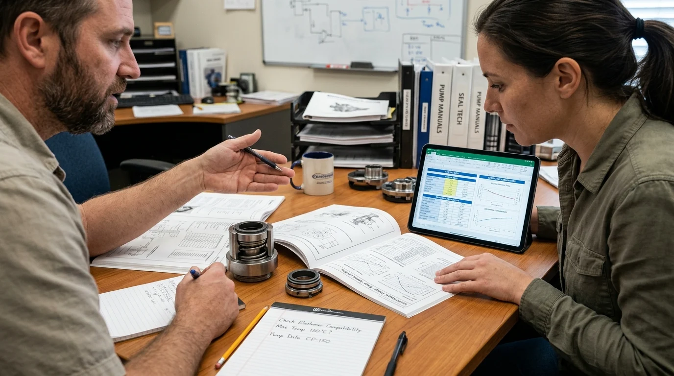
Specifying a seal for a pump handling 300°F caustic soda based solely on flange dimensions or historical purchasing records frequently results in rapid elastomer degradation and catastrophic failure. Accurate and comprehensive operational data prevents such costly misapplications.
Engineers must conduct a thorough system audit to capture the exact fluid characteristics and mechanical dynamics present at the stuffing box, aligning the seal’s metallurgical and elastomeric properties with the realities of the process environment.
Fluid properties, pressure, and temperature
Critical data points for seal selection include the fluid’s specific gravity, vapor pressure at operating temperature, viscosity, and the presence of suspended solids. Vapor pressure is particularly crucial; if the fluid flashes to a gas at the seal faces, the resulting lack of lubrication causes immediate dry-running failure.
Operating pressure and temperature establish the structural requirements of the seal components. For instance, stuffing box pressures exceeding 400 psig (27.5 bar) or fluid temperatures climbing above 400°F (204°C) strictly dictate specialized architectures, such as high-pressure balanced designs and secondary containment systems utilizing high-temperature perfluoroelastomers (FFKM) or flexible graphite.
Pump speed, shaft movement, and duty cycle
The rotational speed (RPM) of the pump determines the sliding velocity at the seal faces, directly impacting heat generation and wear rates. High-speed applications require specialized face materials with exceptional thermal conductivity, such as silicon carbide.
Shaft movement, including radial deflection and axial end-play, must be quantified. Shaft deflection greater than 0.002 inches (0.05 mm) at the seal face can cause the faces to separate momentarily, allowing particulate ingress and premature wear. Furthermore, understanding the duty cycle—whether the pump operates continuously, intermittently, or experiences frequent start-stop cycles—helps in specifying a seal capable of handling these repeated mechanical stresses.
Packing, single seals, and double seals
Engineers must choose between traditional compression packing, single mechanical seals, and dual (double) mechanical seals based on containment needs. While packing is cost-effective upfront, it requires continuous weeping for lubrication, making it unsuitable for hazardous or high-value fluids. Single mechanical seals offer virtually leak-free operation under normal conditions but lack a backup containment layer.
Double mechanical seals utilize a barrier fluid to provide a secondary line of defense, ensuring that any primary seal leakage is contained within the support system. This arrangement is mandatory for highly toxic or lethal services where atmospheric exposure poses immediate life-safety risks. However, double seals introduce operational complexity, requiring rigorous barrier fluid maintenance and carrying a potential risk of cross-contamination if the barrier fluid enters the process stream.
Alternatively, for the most hazardous services, engineers may bypass mechanical seals entirely by selecting sealless pump technologies, such as magnetic drive or canned motor pumps. While these eliminate dynamic seal leakage risks, they introduce different engineering trade-offs regarding upfront cost, fluid temperature limits, and sensitivity to dry running.
| Containment Technology | Typical Leakage Rate | Friction / Energy Loss | Initial Capital Cost | Ideal Application Profile |
|---|---|---|---|---|
| Compression Packing | 10 to 60 drops per minute | High | Low | Benign fluids, cooling water |
| Single Mechanical Seal | < 0.1 drops per minute | Moderate | Medium | Non-hazardous chemicals |
| Double Mechanical Seal | Zero atmospheric emissions | Moderate to High | High | Toxic, volatile, or abrasive fluids |
How to Compare Seal Technologies
The operational data collected in the previous phase directly informs the comparison criteria used to evaluate different seal technologies. With numerous configurations and material combinations available, engineers must match the specific capabilities of each seal type against the precise demands of the pumping application.
This evaluation involves analyzing the mechanical actuation mechanisms, the tribological properties of the seal faces, and the necessity of external support systems to maintain an optimal operating environment at the seal chamber.
Seal type comparison criteria
A primary mechanical distinction lies between pusher and non-pusher seal designs. Pusher seals utilize a dynamic O-ring that moves along the shaft to compensate for face wear, which can lead to shaft fretting if the fluid contains abrasives. Non-pusher seals, utilizing metal or elastomeric bellows, eliminate this dynamic secondary seal, offering superior performance in high-viscosity or dirty services.
Hydraulic balancing is another critical comparison criterion. Unbalanced seals are subjected to the full hydraulic force of the stuffing box pressure, which typically limits their application to pressures of 100 to 150 psig (6.9 to 10.3 bar) before the fluid film between the faces collapses. Conversely, balanced seals feature a stepped face geometry that reduces the closing force, allowing them to reliably handle pressures ranging from 400 to 600 psig (27.5 to 41.3 bar) and beyond without excessive heat generation.
Face, elastomer, and metal material compatibility
Seal face materials dictate the tribological success of the installation. Carbon graphite is widely used for its excellent self-lubricating properties, but it lacks the hardness required for abrasive slurries. For severe duties, a combination of Silicon Carbide against Tungsten Carbide provides extreme hardness and thermal conductivity, resisting both physical wear and thermal shocking.
Elastomer selection is equally critical to prevent chemical degradation. Standard Fluoroelastomers (FKM) are suitable for many general industrial applications, but aggressive solvents, amines, or high-temperature steam require advanced Perfluoroelastomers (FFKM). The metallurgy of the seal hardware—typically 316 Stainless Steel—must also be upgraded to duplex stainless steels, Hastelloy, or Titanium when pumping highly corrosive media like concentrated chlorides or sulfuric acid.
Flush plans, barrier fluids, and quench systems
Mechanical seals depend heavily on environmental controls defined by API 682 piping plans. A basic Plan 11 utilizes a bypass line from the pump discharge to flush the seal faces, removing generated heat. However, for fluids that polymerize or crystallize upon atmospheric contact, a Plan 62 quench system is deployed to introduce low-pressure steam or water to wash away deposits on the atmospheric side of the seal.
For dual seal configurations, barrier fluid systems (such as Plan 53A, 53B, or 54) are mandatory. A Plan 53A pressurized barrier system requires the barrier fluid pressure to be maintained at least 20 to 25 psig (1.4 to 1.7 bar) above the maximum seal chamber pressure. This pressure differential ensures that any face leakage migrates into the process fluid, absolutely preventing the hazardous process medium from entering the barrier system or the atmosphere.
Compliance, Reliability, and Cost Factors
Focusing exclusively on the initial purchase price of a mechanical seal often compromises safety and inflates lifecycle costs. Engineering managers must evaluate seal selection through the lens of Total Cost of Ownership (TCO), balancing stringent regulatory compliance with long-term mechanical reliability. This requires factoring in historical asset performance, industry standards, and hidden maintenance and energy costs.
Industry standards and site requirements
Adherence to recognized engineering standards is non-negotiable in critical process industries. API 682 (ISO 21049) is the definitive standard for mechanical seals in the petroleum, natural gas, and chemical sectors, dictating rigorous testing, material traceability, and standardized seal chamber dimensions. It is important to note that API 682 primarily serves these heavy industries and is not universally applicable to all industrial pumps, such as those used in municipal water or food and beverage applications, which follow different sanitary or utility standards.
Environmental compliance further shapes seal selection. Regulatory bodies heavily monitor Volatile Organic Compound (VOC) emissions from rotating equipment. For example, EPA Method 21 sets strict VOC leak thresholds for refineries and chemical plants, often requiring emissions to remain below 500 parts per million by volume (ppmv). Achieving and maintaining these ultra-low emission targets mandates the use of precision-engineered dual seals with optimized barrier systems.
Reliability indicators and maintenance history
Historical maintenance data serves as an invaluable diagnostic tool when specifying replacement seals. Tracking the Mean Time Between Repairs (MTBR) for individual pump assets highlights chronic bad actors within the plant. If a specific pump consistently exhibits an MTBR of less than 12 months, simply replacing the seal in-kind is a failure of engineering oversight.
Analyzing the failure modes of the extracted seals—whether it be thermal cracking, elastomer extrusion, or abrasive scoring—provides the necessary evidence to upgrade the seal metallurgy or modify the environmental control plan. Reliability indicators must drive continuous improvement, shifting the maintenance paradigm from reactive firefighting to proactive, engineered solutions.
Total cost of ownership versus purchase price
The initial capital expenditure for a mechanical seal represents a fraction of its true financial impact over its operational life. Total Cost of Ownership (TCO) models must incorporate the cost of replacement parts, the labor required for installation, the cost of barrier fluids, and the financial penalty of deferred production during maintenance outages.
Energy consumption is a frequently overlooked component of TCO. The parasitic energy consumed by seal face friction and the thermodynamic losses associated with external flush cooling systems can account for a moderate portion of the total energy usage of the pump. Upgrading to optimized face geometries and efficient barrier systems yields significant energy savings over a typical 5-year operational lifecycle.
While specific TCO breakdowns vary by facility, the following table illustrates a typical 5-year lifecycle cost distribution and mitigation strategies:
| TCO Component | Impact on 5-Year Lifecycle Cost | Mitigation Strategy via Proper Selection |
|---|---|---|
| Initial Hardware Purchase | Minor | Standardize cartridge seals to reduce inventory variants. |
| Energy & Friction Losses | Moderate | Specify balanced seals to lower face loading and friction. |
| Flush / Barrier Fluid Consumption | Moderate | Utilize closed-loop Plan 53B/53C systems to minimize fluid waste. |
| Maintenance Labor & Downtime | Dominant | Select optimal materials to extend MTBR and prevent unplanned outages. |
Practical Selection Workflow
Establishing a formal selection protocol ensures that critical operational variables are never overlooked and that all stakeholders—from process engineering to procurement—are aligned. A rigorous workflow mitigates the risk of human error during specification, streamlines the procurement cycle, and establishes a clear chain of documentation that supports future maintenance and troubleshooting efforts.
Step-by-step selection process
Step one of the selection process involves defining the operating window, meticulously documenting the fluid state, pressure profile, temperature extremes, and pump kinematics. Step two dictates the seal arrangement—deciding between single, dual unpressurized, or dual pressurized configurations based on toxicity and emission limits.
Step three focuses on material selection, cross-referencing chemical compatibility charts to specify the primary faces, secondary elastomers, and metallurgy. Finally, step four involves designing the environmental support system (API piping plan) required to sustain the seal. Adhering to this formal, multi-step engineering review systematically eliminates the root causes of premature mechanical seal failures.
OEM, distributor, and specialist sourcing decisions
Original Equipment Manufacturers (OEMs) provide unparalleled technical expertise and failure analysis capabilities, making them the preferred channel for highly engineered, critical-service applications. However, custom engineered seals from OEMs may carry extensive lead times ranging from 12 to 16 weeks.
For standard utility pumps or aggressive maintenance schedules, utilizing authorized distributors or specifying standardized, off-the-shelf cartridge seals can reduce procurement lead times to just 1 to 2 weeks. Independent seal specialists can also offer valuable reverse-engineering services and rapid prototyping, providing competitive alternatives for legacy equipment where OEM support is no longer viable.
Final decision checklist
Before a purchase order is issued and prior to commissioning, a final technical review must be executed. Use the following checklist to ensure all critical parameters are verified:
Pre-Procurement:
- Verify dimensions: Ensure the selected seal dimensions perfectly match the stuffing box envelope, allowing adequate radial clearance for flush fluids.
- Confirm utilities: Check that the plant’s existing utility infrastructure—such as cooling water, nitrogen, and instrument air—can adequately support the specified API piping plan.
Pre-Startup:
- Check rotation: Post-delivery and prior to startup, maintenance technicians must confirm that the seal cartridge spins freely.
- Inspect hardware: Ensure that all setting clips are intact and properly positioned before operation.
- Archive documentation: Confirm that all material traceability and pre-installation documentation is properly archived for future reference.
Comprehensive documentation ensures that the rigorous engineering effort invested in the selection process translates into tangible, long-term reliability on the plant floor.
Ultimately, treating mechanical seal selection as a rigorous engineering process establishes a foundation for continuous improvement. As facilities integrate more IoT sensors and condition-monitoring tools, the data feedback loop from operating seals will increasingly drive predictive maintenance and refine future specifications. By leveraging these evolving technologies alongside comprehensive system audits, plants can adapt to changing process demands and achieve sustained reliability.
Key Takeaways
- Collect complete operating data before selection, including fluid chemistry, vapor pressure, viscosity, solids content, pressure, temperature, and shaft speed.
- Evaluate vapor pressure at operating temperature because flashing at the seal faces can cause immediate dry-running damage.
- Select elastomers and face materials for chemical compatibility to prevent swelling, hardening, dissolution, or abrasive grooving.
- Use advanced or double seal arrangements for volatile, toxic, flammable, or emissions-regulated fluids to strengthen containment.
- Treat seal selection as a reliability decision because unplanned pump downtime in continuous process plants can reach an estimated $10,000 to $50,000 per hour.
Frequently Asked Questions
What operating data is needed before selecting a mechanical seal?
Gather fluid chemistry, specific gravity, vapor pressure, viscosity, solids content, stuffing box pressure, temperature, shaft speed, and any flush or cooling requirements. These details determine seal face materials, elastomers, metallurgy, and seal arrangement.
Why do mechanical seals fail in industrial pump systems?
Most failures come from misapplication rather than manufacturing defects. Common causes include dry running, incorrect elastomer compatibility, abrasive slurry wear, poor flush planning, excessive heat, and operating pumps beyond their original pressure or temperature limits.
How does vapor pressure affect seal selection?
If a liquid flashes to vapor at the seal faces, lubrication disappears and dry-running damage can occur quickly. Vapor pressure must be checked at actual operating temperature so engineers can choose the right seal design and support system.
When should a facility consider double mechanical seals?
Double seals are often used for toxic, volatile, flammable, or environmentally restricted fluids. They provide an added containment barrier and can support zero-emissions goals when paired with the correct barrier or buffer fluid system.
How can proper seal selection reduce operating costs?
Correct selection improves MTBF, reduces product loss, limits fugitive emissions, and helps avoid unplanned downtime. In continuous process plants, severe pump outages may cost an estimated $10,000 to $50,000 per hour, depending on the operation.

Post time: Aug-15-2026