


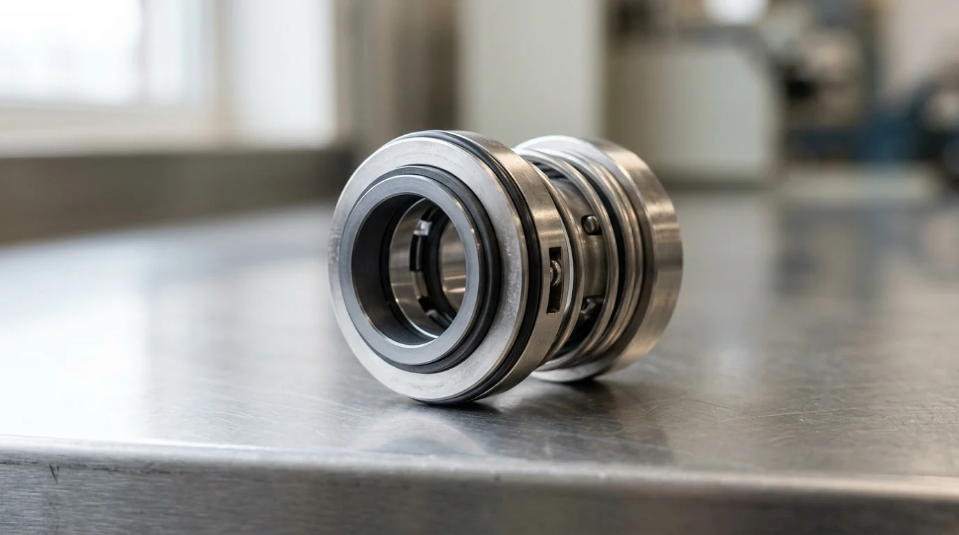
Why Mechanical Seals Matter in Refinery Pump Applications
In modern petroleum refining, centrifugal pumps are the primary fluid movers driving process fluids through distillation columns, catalytic crackers, and treatment units. The integrity of these pumping systems relies heavily on their sealing technology. Mechanical seals form the primary barrier between highly volatile, toxic, or high-temperature process fluids and the external atmosphere. Selecting the correct mechanical seals for refinery pump applications is not merely a maintenance consideration; it is a fundamental engineering requirement that dictates unit availability, environmental compliance, and site safety.
Increasingly stringent emission regulations and the demand for longer uninterrupted operational cycles drive the evolution of refinery sealing technology. Rather than focusing solely on the risk of catastrophic failures, modern engineering approaches prioritize continuous containment and reliability. Specifying mechanical seals requires a rigorous evaluation of fluid thermodynamics, equipment dynamics, and long-term lifecycle objectives to solve complex fluid containment challenges.
Mechanical Seals as Reliability-Critical Components
Within the hierarchy of rotating equipment components, mechanical seals disproportionately cause pump downtime. Industry reliability studies consistently indicate that mechanical seal failures account for 60% to 70% of all centrifugal pump maintenance interventions. This high failure attribution stems from the delicate nature of seal faces, which operate with a fluid film thickness typically ranging from 0.25 to 1.5 micrometers. Maintaining this microscopic gap under varying dynamic loads requires exact engineering tolerances.
To mitigate these vulnerabilities, the American Petroleum Institute (API) established the API 682 standard, which mandates a minimum Mean Time Between Failures (MTBF) of 25,000 hours (approximately three years) of continuous operation for refinery seals. Achieving this 25,000-hour baseline requires seal designs that can accommodate shaft deflection, thermal expansion, and transient pressure spikes without compromising the sealing interface of the seal faces. Engineers must therefore treat mechanical seals not as commoditized wear parts, but as highly engineered, reliability-critical assets.
Refinery Pump Risks That Influence Seal Selection
Refinery environments expose mechanical seals to an extreme spectrum of operational risks. High-temperature services, such as vacuum distillation bottoms or catalytic slurry pumps, frequently subject seals to fluid temperatures exceeding 350°C (660°F). At these temperatures, thermal distortion of the seal faces and the degradation of secondary elastomeric elements become primary failure modes. Conversely, light hydrocarbon services, such as ethane or propane pumps, operate at high pressures but low temperatures, presenting severe risks of fluid vaporization across the seal faces, leading to dry running and immediate failure.
Toxicity and flammability are equally critical risk vectors. The presence of hydrogen sulfide (H2S), benzene, and hydrofluoric acid necessitates absolute containment. Fugitive emission regulations, such as the U.S. EPA’s Method 21, strictly limit Volatile Organic Compound (VOC) emissions to below 500 parts per million by volume (ppmv), with some local jurisdictions enforcing limits as low as 100 ppmv. Selecting a seal configuration must account for these hazards, often driving the specification toward complex dual-seal arrangements with dedicated barrier fluid systems to ensure zero process leakage to the atmosphere.
Operating Conditions to Define Before Seal Selection

The specification of a mechanical seal begins with a comprehensive definition of the operating boundary conditions. Engineering a reliable sealing solution is impossible without an exact understanding of the fluid’s thermodynamic state at the seal chamber, the mechanical constraints of the pump, and the overarching service classification. These parameters dictate the seal’s fundamental geometry, material composition, and required auxiliary support.
Process Variables That Determine Seal Design
The primary process variables dictating seal design are fluid pressure, temperature, specific gravity, viscosity, and vapor pressure. Seal chamber pressure directly influences the closing forces on the seal faces; excessive pressure can cause face distortion or extrusion of secondary O-rings. Refineries routinely operate pumps with seal chamber pressures ranging from sub-atmospheric vacuums to over 40 bar (600 psi). Additionally, the fluid’s vapor pressure margin—the difference between the seal chamber pressure and the fluid’s vapor pressure at the pumping temperature—is critical. A minimum vapor pressure margin of 3.5 bar (50 psi) or a temperature margin of 20°C is generally required to prevent flashing at the seal faces.
Viscosity and particulate concentration further constrain the design. Highly viscous fluids (exceeding 3,000 cSt) can generate excessive shear heat and torque, requiring robust drive mechanisms and heavy-duty face materials. If the process fluid contains abrasive catalyst fines or coke particles, the seal must utilize hard-on-hard face combinations and specialized flushing arrangements to prevent rapid abrasive wear of the primary sealing surfaces.
Refinery Service Categories for Mechanical Seals
To standardize selection, API 682 categorizes mechanical seals based on the severity of the service and the type of equipment. Understanding these categories is essential for matching the seal’s robustness to the application’s demands.
| API 682 Category | Shaft Size Range | Max Temperature | Max Pressure | Typical Application |
|---|---|---|---|---|
| Category 1 | 20 to 110 mm | -40°C to 260°C | 20 bar (300 psi) | Non-API 610 pumps, general refinery duty |
| Category 2 | 20 to 110 mm | -40°C to 400°C | 40 bar (600 psi) | API 610 pumps, heavy-duty hazardous fluids |
| Category 3 | 20 to 110 mm | -40°C to 400°C | 40 bar (600 psi) | Most demanding services, rigorous qualification testing |
Category 1 seals are typically deployed in off-site or utility applications where temperatures and pressures are moderate. Category 2 seals represent the standard for the majority of API 610 process pumps within the process unit boundaries of the refinery. Category 3 seals share the same operational limits as Category 2 but mandate stricter design documentation, tighter clearances, and more rigorous qualification testing, making them the default choice for highly critical or highly hazardous process streams.
It is important to note that these categories have limitations. API 682 is specifically designed for horizontal centrifugal pumps constructed to API 610 standards. Non-API 610 pumps and vertical turbine pumps, which are common in refinery cooling water and utility services, do not map cleanly to the Category 1, 2, or 3 framework. Applying API 682 guidelines to these equipment types requires engineering judgment beyond standard parameters to ensure adequate seal life.
Pump and Equipment Data Required for Specification
Beyond fluid properties, the mechanical dimensions and dynamic behavior of the pump hardware must be precisely defined. The shaft diameter at the seal chamber, which in refineries typically ranges from 20 mm to over 150 mm, dictates the physical size and rotational velocity of the seal components. High rotational speeds generate significant centrifugal forces and shear heat, necessitating balanced seal designs that minimize the hydraulic load on the faces.
The dimensions of the pump’s stuffing box or seal chamber limit the physical envelope available for the mechanical seal. Modern API 610 pumps feature enlarged seal chambers designed specifically to accommodate robust cartridge seals, but retrofitting older equipment often requires custom-engineered seals to fit constrained spaces. Furthermore, equipment condition data—such as maximum allowable shaft runout (typically limited to 0.05 mm or 0.002 inches) and axial endplay—must be verified, as excessive vibration will prematurely destroy even the most precisely specified mechanical seal.
Mechanical Seal Designs, Materials, and Support Systems
Once the operating conditions are fully defined, the selection process transitions to specifying the physical architecture of the seal. This involves configuring the seal arrangement, selecting the optimal materials for both the primary faces and secondary elastomers, and integrating the appropriate API piping plan to manage the environment immediately surrounding the seal.
Seal Arrangements to Compare
API 682 classifies mechanical seals into three primary arrangements, each offering progressive levels of containment and complexity. Arrangement 1 consists of a single seal per cartridge. While cost-effective and simple to maintain, a failure of an Arrangement 1 seal results in direct leakage of the process fluid to the atmosphere, limiting its use to non-hazardous, non-volatile fluids where minor fugitive emissions are acceptable.
Arrangement 2 utilizes two seals in series with an unpressurized buffer fluid between them. The inner seal handles the full process pressure, while the outer seal acts as a safety backup. If the inner seal fails, the outer seal contains the leakage, directing it to a liquid collection system or flare. Arrangement 3 provides the highest level of security, utilizing two seals separated by a pressurized barrier fluid. Because the barrier fluid is maintained at a pressure higher than the process fluid (typically 1.5 to 2 bar above seal chamber pressure), any leakage across the inner faces results in clean barrier fluid entering the pump, guaranteeing zero process emissions to the atmosphere.
For specific pump applications involving highly volatile, flashing light hydrocarbons, pump-specific dry gas seals present a viable alternative to traditional liquid-lubricated mechanical seals. These seals utilize a pressurized inert gas (typically nitrogen) to create a non-contacting aerodynamic fluid film between the seal faces. While they require sophisticated gas conditioning panels, they eliminate the need for complex liquid barrier systems and effectively prevent fugitive emissions in volatile pump services.
Seal Face, Elastomer, and Metal Material Selection
Material selection is paramount for achieving long-term reliability targets. For primary seal faces, the industry standard has shifted heavily toward Silicon Carbide (SiC) due to its exceptional hardness, high thermal conductivity, and broad chemical resistance. In highly abrasive services, Tungsten Carbide (WC) may be paired with SiC. Carbon graphite is frequently used as a mating face in clean, lubricating fluids because of its excellent dry-running survivability and self-lubricating properties.
Secondary sealing elements, specifically O-rings, are frequently the weakest link in high-temperature applications. Standard Fluoroelastomers (FKM, e.g., Viton) are generally limited to 200°C (392°F). For higher temperatures or aggressive chemicals, Perfluoroelastomers (FFKM, e.g., Kalrez) are required. FFKM compounds can withstand temperatures up to 327°C (620°F) and resist virtually all refinery chemicals, though they cost significantly more than standard elastomers. For temperatures between 327°C and 400°C, engineers typically transition to flexible graphite secondary seals paired with metal bellows. Metal bellows seals, utilizing high-nickel alloys like Inconel 718, eliminate dynamic O-rings entirely, making them the preferred choice for extreme temperature services exceeding 400°C (750°F).
How API Piping Plans Influence Seal Choice
Mechanical seals cannot survive without a precisely controlled micro-environment, which is provided by API 682 Piping Plans. These support systems dictate how fluid is routed to the seal to provide cooling, lubrication, and flushing of contaminants.
| API Piping Plan | Seal Arrangement | Description | Typical Use Case |
|---|---|---|---|
| Plan 11 | Arrangement 1 | Flush from pump discharge to seal | Standard clean fluids, heat removal |
| Plan 52 | Arrangement 2 | Unpressurized external reservoir | Flammable/toxic fluids needing containment |
| Plan 53A | Arrangement 3 | Pressurized external barrier fluid | Zero emissions, hazardous/abrasive fluids |
| Plan 32 | Arrangement 1 or 2 | Injection of clean external fluid | Highly abrasive or crystallizing fluids |
Selecting the correct piping plan is as critical as selecting the seal itself. For instance, a Plan 11 is sufficient for a clean, cool hydrocarbon, but a Plan 53A is mandatory for an Arrangement 3 seal handling highly toxic H2S. The support system also introduces maintenance variables; a Plan 53A requires operators to monitor barrier fluid levels and maintain nitrogen pressurization, adding operational complexity in exchange for absolute emission control.
Compliance, Reliability, and Lifecycle Cost Factors
In the highly regulated hydrocarbon processing industry, mechanical seal selection extends beyond pure mechanical engineering. Engineers must balance strict environmental compliance mandates with the overarching goals of maximizing equipment reliability and optimizing the Total Cost of Ownership (TCO) over the lifecycle of the pumping system.
Standards and Regulatory Drivers for Refinery Seals
Regulatory compliance is a primary driver in refinery seal selection. Environmental protection agencies globally enforce stringent limits on volatile organic compound (VOC) emissions to mitigate air pollution and greenhouse gas accumulation. In the United States, the EPA’s National Emission Standards for Hazardous Air Pollutants (NESHAP) and specific local regulations dictate leak detection and repair (LDAR) protocols.
Under these standards, a seal leaking above the established LDAR threshold is classified as a failure, triggering mandatory repair timelines and potential fines. Single seals (Arrangement 1) often struggle to consistently maintain these strict emission limits over a multi-year run. Consequently, compliance drivers frequently force refineries to upgrade to Arrangement 2 or Arrangement 3 dual seals, which structurally guarantee compliance by utilizing the buffer or barrier fluids discussed earlier to isolate the process fluid from the atmosphere.
Lifecycle Cost Evaluation for Mechanical Seals
When evaluating mechanical seals, reliance on initial capital expenditure (CAPEX) is a severely flawed metric. Lifecycle cost analysis reveals that the initial purchase price of a mechanical seal typically represents only 10% to 20% of its total cost of ownership over a 10-year span. The remaining 80% to 90% is comprised of operational expenditures (OPEX), including barrier fluid consumption, support system maintenance, energy consumed by seal face friction, and the significant costs of unplanned pump downtime.
For example, utilizing a Plan 32 flush (injecting clean, external fluid into the seal chamber) may allow the use of a cheaper Arrangement 1 seal in a dirty service. However, if that flush fluid flows at 10 liters per minute, the refinery must pay to heat, pump, and eventually separate or distill millions of liters of flush fluid annually. Upgrading to a more expensive Arrangement 3 seal with a Plan 53A closed-loop barrier system eliminates this massive energy and processing penalty, resulting in a significantly lower lifecycle cost despite a higher initial CAPEX.
Trade-Offs Between Reliability, Cost, and Maintainability
Selecting the optimal seal requires navigating inherent trade-offs between reliability, upfront cost, and maintainability. A dual pressurized seal (Arrangement 3) provides the ultimate reliability and zero emissions, but it requires a complex barrier fluid reservoir, pressure tracking instrumentation, and rigorous operator training. If the barrier pressure is lost, the seal will fail rapidly. Therefore, the highest-technology seal may actually reduce overall system reliability if the plant’s maintenance culture cannot support the required auxiliary systems.
Conversely, standardizing on simpler, robust single seals (Arrangement 1) with high-grade silicon carbide faces and perfluoroelastomers can maximize maintainability and reduce operator error. Engineers must assess the criticality of the specific pump. For a critical unspared charge pump, the complexity and cost of an Arrangement 3 system are easily justified by the prevention of a $500,000-per-day unit outage. For a spared utility pump, a highly maintainable Arrangement 1 seal provides the best balance of cost and reliability.
Decision Process for Selecting Mechanical Seals
Translating fluid properties, environmental regulations, and lifecycle economics into a final procurement specification requires a structured decision-making process. By following a systematic workflow, reliability engineers and procurement teams can ensure that the selected mechanical seal meets both the immediate technical requirements and the long-term operational goals of the refinery.
Step-by-Step Seal Selection Workflow
The seal selection workflow should follow a deterministic path, typically beginning with the API 682 selection methodology. Step one is fluid characterization: defining the vapor pressure margin, toxicity, and particulate content to establish the required API Service Category (1, 2, or 3). Step two determines the Seal Arrangement (1, 2, or 3) based strictly on local emission regulations and the fluid’s safety profile.
Step three involves selecting the seal configuration type (Type A, B, or C). Type A features pusher-type O-rings, Type B utilizes elastomer bellows, and Type C relies on high-temperature metal bellows. Step four dictates the material selection for faces and secondary seals based on maximum operating temperature and chemical compatibility. The final step is engineering the environmental control system, selecting the appropriate API Piping Plan to ensure the seal faces remain cool, clean, and adequately lubricated under all transient conditions.
Standardization Versus Service-Specific Selection
A major strategic decision for refinery reliability managers is balancing service-specific optimization against plant-wide standardization. Custom-engineering a seal for every individual pump ensures perfect application fit but results in a massive, unmanageable inventory of spare parts. Inventory carrying costs in the refining sector represent a substantial annual expense. Maintaining hundreds of unique seal SKUs ties up significant capital and increases the risk of installing incorrect replacement parts during a midnight turnaround.
To combat this, modern refineries actively pursue standardization programs. By standardizing on a robust, highly capable seal—such as an API 682 Category 2, Type A cartridge seal with Silicon Carbide faces and FFKM elastomers—a plant can cover 70% to 80% of its pump population with a limited number of SKUs. While this approach means some seals will be technically “over-specified” for benign water or light utility services, the reduction in inventory carrying costs (often significantly reducing the overall SKU count) and the elimination of maintenance errors far outweigh the higher unit cost of the standardized seal.
However, standardization has limits. Forcing standard seals onto older, non-standard equipment often requires costly pump casing or stuffing box modifications. In scenarios where machining the pump to accept a standard cartridge seal is prohibitively expensive or structurally unfeasible, custom-engineered seals remain the more practical and cost-effective choice.
Final Selection Guidance for Engineers
For engineers finalizing mechanical seal specifications, collaboration with the original equipment manufacturer (OEM) is critical. To ensure a rigorous procurement process, engineers should utilize a decisive technical checklist:
- Demand rigorous performance predictions: Require OEMs to provide specific calculation methodologies for face-generated heat, estimated barrier fluid consumption rates, and expected torque requirements under the specified operating conditions.
- Verify qualification testing: Specify that seals must meet API 682 Annex F test protocols to ensure they have been proven under representative dynamic conditions.
- Review historical MTBF data: Evaluate the proposed seal design’s field performance in identical refinery services.
- Integrate condition monitoring: Incorporate proactive detection strategies—such as continuous vibration analysis, seal pot level and pressure monitoring, and acoustic emission sensors—to identify degrading seal faces or failing support systems before they result in a catastrophic breach.
Ultimately, the goal is to shift the engineering focus from reacting to seal failures to proactively designing them out of the system.
Key Takeaways
- Treat mechanical seals as reliability-critical refinery assets because they are linked to 60% to 70% of centrifugal pump maintenance interventions.
- Specify refinery seals against defined process conditions, including fluid composition, vapor pressure, temperature, pressure, shaft speed, solids, and operating transients.
- Use API 682 as the baseline for refinery pump seal design, qualification, piping plans, and the 25,000-hour minimum MTBF expectation.
- Select dual seals with suitable barrier or buffer systems for toxic, volatile, flammable, or emissions-regulated services such as H2S, benzene, and light hydrocarbons.
- Match seal face materials, elastomers, and flush plans to thermal risk because refinery services may exceed 350°C and cause face distortion or secondary seal degradation.
Frequently Asked Questions
Why are mechanical seals so critical in refinery pump applications?
Mechanical seals are the primary containment barrier between hazardous refinery fluids and the atmosphere. Because seal failures can drive 60% to 70% of centrifugal pump maintenance interventions, correct selection directly affects uptime, emissions compliance, safety, and lifecycle cost.
What operating data should be defined before choosing a refinery pump seal?
Define fluid composition, vapor pressure, temperature, pressure, shaft speed, solids content, toxicity, flammability, start-stop frequency, and expected transients. These details determine seal face materials, elastomers, spring design, flush plan, and whether a single or dual seal is appropriate.
When should a refinery use a dual mechanical seal?
Dual seals are preferred for toxic, flammable, volatile, or environmentally regulated services such as benzene, H2S, light hydrocarbons, or hydrofluoric acid. They use buffer or barrier fluids to reduce or prevent process leakage to the atmosphere.
What does API 682 mean for refinery mechanical seals?
API 682 is the key refinery seal standard. It sets requirements for seal design, qualification, materials, piping plans, and reliability, including a target minimum mean time between failures of 25,000 hours under suitable operating conditions.
How do high temperatures affect mechanical seal selection?
High-temperature services can distort seal faces, coke process fluids, and degrade elastomers. Engineers should select compatible face materials, high-temperature secondary seals, proper cooling or flush plans, and designs that maintain a stable fluid film.

Post time: Oct-11-2026