


Why Single Spring Mechanical Seals Fail in Centrifugal Pumps
In the realm of rotating equipment, centrifugal pumps rely heavily on mechanical seals to contain process fluids, maintain system pressure, and prevent environmental contamination. Among the various sealing technologies, single spring mechanical seals are the most ubiquitous due to their robust design, cost-effectiveness, and tolerance for heavily contaminated fluids. However, despite their widespread adoption, mechanical seal failures account for an estimated 70 to 80 percent of all centrifugal pump maintenance interventions, though this illustrative figure varies significantly depending on the industry, pump type, and facility maintenance practices. Understanding why these specific seals fail requires a deep dive into their mechanical architecture, the operational limits of a single-coil design, and the subtle indicators of impending breakdown.
Single spring seals are engineered to handle a broad spectrum of industrial applications, from wastewater management to chemical processing. Yet, their simplicity is often a double-edged sword. When applied outside their strict operational parameters, the very design features that make them durable—such as a large, heavy-gauge coil spring—can become the root cause of catastrophic failure. Analyzing these failures demands a rigorous evaluation of mechanical forces, hydraulic conditions, and material science.
How Single Spring Mechanical Seals Work
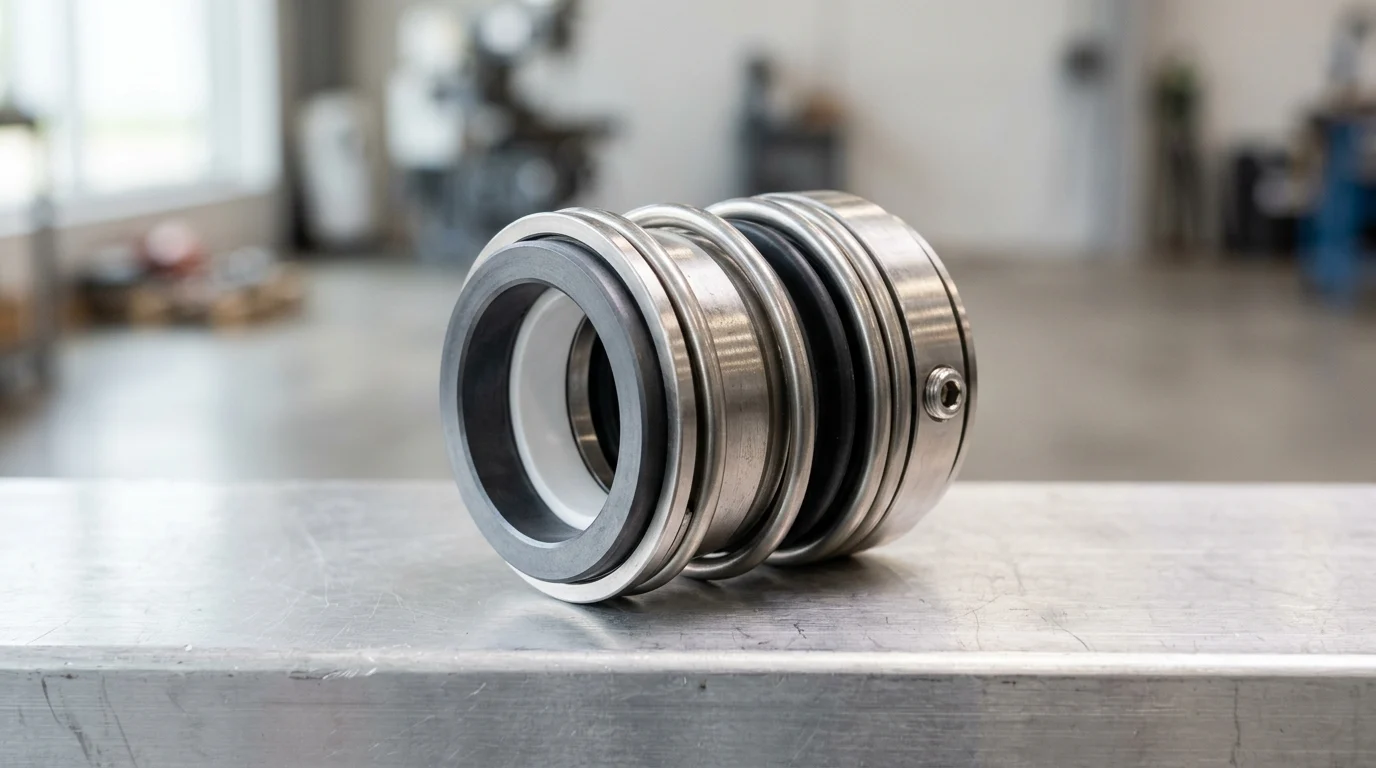
At its core, the architecture of a single spring mechanical seal consists of a primary rotary ring, a stationary mating ring, secondary sealing elements (elastomeric O-rings, V-rings, or wedges), and a single, large-diameter coil spring. The primary function of the spring is to provide continuous mechanical closing force against the seal faces, ensuring they remain in contact during pump startup, shutdown, and periods of zero hydraulic pressure. This mechanical loading typically ranges from 15 to 30 psi (approximately 1 to 2 bar), depending on the seal size and manufacturer specifications.
Once the centrifugal pump reaches its operating speed and the casing is pressurized, hydraulic forces take over as the primary mechanism keeping the seal faces closed. The process fluid penetrates the microscopic gap between the highly lapped seal faces, creating a lubricating fluid film that is usually less than 1 micron thick. The single spring must maintain enough tension to prevent the faces from blowing open under pressure fluctuations, while simultaneously allowing enough flexibility for the rotary face to track any microscopic axial shaft movement.
Where Seals Reach Their Design Limits
While robust, single spring mechanical seals possess inherent design limitations, particularly concerning high-speed operations and uniform face loading. Because the single spring is manufactured from a continuous, thick-gauge wire coiled around the shaft, it is subject to significant centrifugal forces. At high shaft speeds—typically exceeding 3,600 RPM or peripheral speeds of 4,500 feet per minute (fpm) (approximately 22.8 meters per second)—the large spring can begin to uncoil or distort. This physical distortion alters the mechanical load applied to the seal faces, leading to premature leakage.
Furthermore, unlike multi-spring designs that distribute mechanical load evenly across 360 degrees of the seal face, a single spring applies force from a singular directional coil. This can create slight localized pressure differentials. When process pressures exceed approximately 150 to 200 psi (10 to 14 bar) in an unbalanced configuration, the combined hydraulic and mechanical closing forces generate excessive friction, pushing the seal past its operational Pressure-Velocity (PV) limit and causing rapid face degradation.
Leakage Patterns That Signal Failure
Differentiating between normal operational weeping and pathological leakage is critical for early failure detection. By design, all mechanical seals leak a microscopic amount of fluid to lubricate the faces; in a healthy single spring seal, this leakage typically evaporates immediately, manifesting as an invisible vapor. Normal volumetric leakage is mathematically negligible, typically estimated between 0.005 and 0.010 ml/hr per millimeter of shaft diameter according to manufacturer guidelines.
In the field, operators cannot easily measure such microscopic amounts; instead, they monitor for visible changes. When failure initiates, the transition is stark. A steady, visible drip rate—often defined practically as exceeding approximately 60 drops per minute (roughly 3 to 4 ml/min)—generally indicates a compromised secondary elastomer or moderate face scoring. If the leakage presents as a continuous stream or a sudden, pressurized spray, it signals a catastrophic loss of the fluid film, a shattered seal face, or a completely collapsed spring. Intermittent leakage that occurs only during pump startup or shutdown often points to a loss of spring elasticity or a hung-up rotary face that is failing to track the stationary ring under low-pressure conditions.
Common Pump Operating Conditions That Cause Seal Failure
The longevity of a single spring mechanical seal is inextricably linked to the hydraulic conditions within the centrifugal pump. Even the most precisely engineered seal will fail rapidly if subjected to aggressive operational deviations. Pump operators must recognize that mechanical seals are not standalone components; they are highly sensitive instruments that react immediately to changes in fluid dynamics, mechanical integrity, and system thermodynamics. When a pump operates outside its Best Efficiency Point (BEP), the resulting instability directly attacks the seal faces and the spring mechanism.
Dry Running, Cavitation, and Vaporization
The most destructive operational condition for any mechanical seal is dry running. The 1-micron fluid film between the seal faces is critical for lubrication and heat dissipation. If the pump loses prime, or if the fluid flashes to vapor, this lubricating film collapses. In a dry run scenario, the coefficient of friction skyrockets, causing localized face temperatures to spike by an estimated 300°F to 500°F (149°C to 260°C) within seconds. This thermal shock can shatter carbon or silicon carbide faces instantly.
Cavitation and vaporization are equally lethal. Cavitation occurs when the Net Positive Suction Head Available (NPSHa) falls below the Net Positive Suction Head Required (NPSHr), causing vapor bubbles to form and violently implode against pump internals. These implosions send high-frequency shock waves through the shaft, fracturing the brittle seal faces and fatiguing the single spring. Vaporization, or flashing, happens when the fluid temperature exceeds its vapor pressure at the seal chamber. The fluid physically expands between the faces, forcing them apart and destroying the seal’s integrity.
Shaft Runout, Misalignment, and Bearing Looseness
Mechanical seals require a stable, concentric shaft to function correctly. Single spring designs, due to their mass and coil structure, are particularly vulnerable to shaft runout and deflection. The maximum allowable shaft runout for optimal seal life is strictly defined, typically falling between 0.001 and 0.002 inches (0.025 to 0.05 mm) Total Indicator Reading (TIR). When runout exceeds these limits, the heavy single spring is forced to rapidly compress and expand with every revolution to keep the faces closed.
This continuous, rapid cycling—often termed “chattering”—leads to severe metal fatigue in the spring and fretting wear on the shaft or sleeve. Bearing looseness exacerbates this issue. If radial bearing play exceeds 0.002 inches (0.05 mm), the shaft will whip during operation. The single spring cannot react fast enough to accommodate this erratic movement, resulting in the rotary face separating from the stationary face, allowing abrasive particles to enter the critical sealing gap.
Pressure, Temperature, and Speed Extremes
Pushing a centrifugal pump beyond its designed pressure, temperature, or speed thresholds drastically reduces the Mean Time Between Failures (MTBF) for single spring seals. High temperatures degrade secondary elastomers; standard Nitrile (Buna-N) O-rings harden and crack above 250°F (121°C), while prolonged exposure to temperatures exceeding 400°F (204°C) requires specialized perfluoroelastomers (FFKM) or flexible graphite secondary seals.
Pressure limits are dictated by the seal’s balance ratio. Unbalanced single spring seals are highly sensitive to pressure surges.
| Operating Parameter | Unbalanced Single Spring Limit | Balanced Single Spring Limit | Impact of Exceeding Limit |
|---|---|---|---|
| Maximum Pressure | 150 – 200 psi (10 – 14 bar) | Up to 400 psi (28 bar) | Excessive face friction, rapid wear, thermal cracking |
| Maximum Speed | 3,600 RPM / 4,500 fpm (22.8 m/s) | 3,600 RPM / 4,500 fpm (22.8 m/s) | Mechanical distortion, dynamic instability |
| Max Temperature (Standard) | 250°F (121°C) (with FKM/Viton) | 400°F+ (204°C+) (with FFKM/Graphite) | Elastomer embrittlement, loss of secondary seal integrity |
Operating beyond these parameters without proper environmental controls (such as API flush plans) guarantees premature failure through mechanical overload or thermal degradation.
Fluid, Material, and Installation Factors
Beyond operational hydraulics, the physical interaction between the pumped media, the seal materials, and the precision of the installation process dictates the ultimate lifespan of a single spring mechanical seal. Selecting a seal based solely on shaft diameter without analyzing the broader context is a guaranteed pathway to premature equipment failure. These failures generally stem from three distinct modes: chemical incompatibility, mechanical abrasion, and human error during assembly.
Seal Face, Elastomer, and Spring Material Compatibility
The chemical composition of the process fluid dictates the material selection for the seal faces, the secondary elastomers, and the spring itself. Elastomer compatibility is frequently mishandled. For example, utilizing a standard Fluorocarbon (FKM/Viton) O-ring in a pump handling low-molecular-weight ketones or esters will result in severe chemical attack. The elastomer absorbs the fluid, causing a volume swell of approximately 20 to 30 percent. This swelling locks the pusher-style rotary face to the shaft, preventing the single spring from advancing the face to compensate for normal wear.
Similarly, the metallurgy of the single spring must resist the corrosive nature of the fluid. While 316 Stainless Steel is the industry standard, pumping high-chloride solutions or strong acids requires upgrading the spring to Hastelloy C-276 or Alloy 20 to prevent chloride stress corrosion cracking. If the spring metal becomes embrittled, it will snap under normal compression forces, instantly removing the mechanical closing load and causing a massive seal blowout.
Abrasive Solids, Crystallization, and Corrosion
Single spring mechanical seals hold a distinct advantage over multi-spring designs when handling abrasive solids, slurries, and crystallizing fluids. Because the single coil is constructed from thick wire with wide spacing, it is highly resistant to clogging. It can typically handle fluids containing up to 10 to 15 percent solids by weight without the spring becoming bound. However, these abrasive particles wreak havoc on the seal faces if the wrong materials are specified.
When pumping abrasive slurries, standard Carbon vs. Ceramic faces will be destroyed by gouging within hours. The specification must be upgraded to hard-on-hard combinations, such as Silicon Carbide (SiC) vs. Silicon Carbide, or Tungsten Carbide (TC). Furthermore, fluids that crystallize upon contact with the atmosphere (like sodium hydroxide or sugar syrups) will form sharp, glass-like deposits on the atmospheric side of the seal. As the single spring attempts to push the rotary face forward as it wears, these crystals tear the secondary O-ring, leading to severe leakage.
Installation Errors That Cause Premature Failure
Human error during the installation of a single spring mechanical seal is a leading cause of infantile failure—where the seal fails within the first 48 hours of operation. The most critical installation metric is the seal’s working length (or operating length). The single spring must be compressed to a very specific dimension to provide the correct 15 to 30 psi (1 to 2 bar) of face loading. The industry standard tolerance for this compression is highly unforgiving, typically requiring accuracy within +/- 0.015 inches (0.38 mm).
If the seal is over-compressed, the excessive mechanical load generates extreme heat, boiling the fluid film and destroying the faces. If under-compressed, the spring fails to keep the faces closed during pressure fluctuations, allowing abrasive particles to enter the sealing gap. Other common installation errors include touching the highly lapped seal faces with bare hands (transferring oils that disrupt the fluid film), failing to properly lubricate the shaft before sliding the O-ring over it, or tightening the gland plate bolts unevenly, which physically distorts the stationary face.
Failure Analysis for Single Spring Mechanical Seals
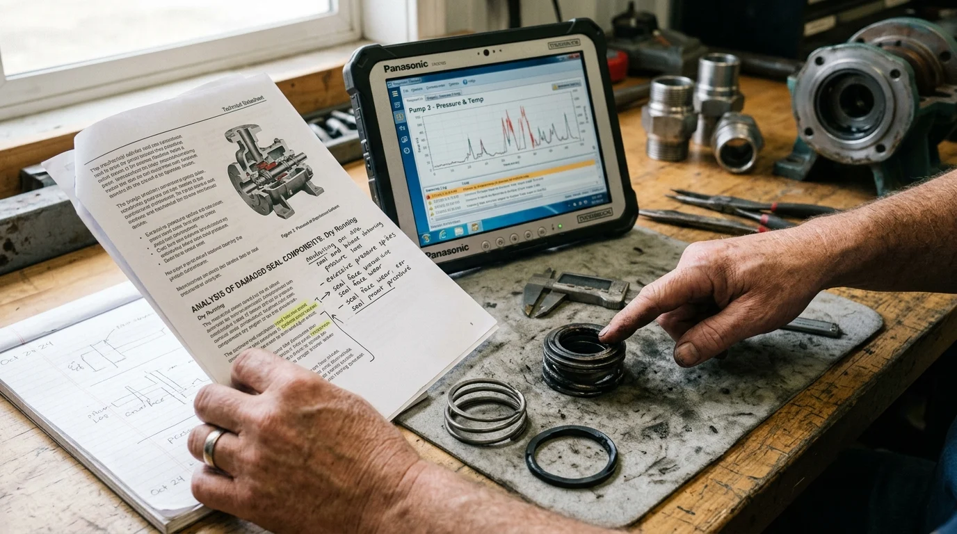
When a single spring mechanical seal fails, the immediate reaction is often to remove the pump from service, strip the seal out, and install a replacement as quickly as possible to minimize downtime. However, this “swap and drop” mentality destroys critical forensic evidence required to identify the root cause of the failure. Implementing a systematic failure analysis protocol ensures that the exact mode of failure is documented, allowing reliability engineers to implement corrective actions rather than simply repeating the same failure cycle.
Evidence to Preserve Before Removing the Seal
The failure analysis begins before the pump is even unbolted from its baseplate. Maintenance personnel must document the physical state of the equipment in its failed condition. The exact location and volume of the leakage path should be photographed. Are there signs of product crystallization on the gland plate? Is the environmental flush line (if equipped) kinked, blocked, or cold to the touch, indicating a lack of flow?
Crucially, before loosening the seal gland, technicians must measure and record the torque on the gland bolts. Uneven bolt torque is a primary cause of stationary face distortion. If one bolt is torqued to 40 ft-lbs (54 N·m) while the opposite is at 15 ft-lbs (20 N·m), the stationary face will warp on a microscopic level, creating a high spot that the rotary face will rapidly wear down. Preserving the exact dimensional setup, including marking the shaft to verify the spring’s working length before removal, is vital for a conclusive autopsy.
How to Inspect Face Wear, Heat Checking, and Spring
Damage
Once the seal is extracted, the condition of the lapped faces tells the story of the failure. A healthy seal will display a uniform, highly polished 360-degree wear track that is typically the exact width of the narrower seal face. To verify flatness, faces are inspected under a monochromatic light source using an optical flat. A seal face should generally be flat within 2 to 3 light bands (approximately 23.2 to 34.8 microinches or 0.59 to 0.88 microns). If the wear track is wider than the face, or if the light bands show severe distortion, the pump shaft was likely suffering from excessive runout.
Heat checking is another critical indicator, presenting as 5 to 20 fine radial cracks originating from the center of the seal face and extending outward. This is undeniable proof of thermal shock, confirming the seal experienced dry running or vaporization. Additionally, inspect the pump shaft or sleeve under the secondary O-ring. A deep groove (fretting) greater than 0.005 inches (0.13 mm) in depth indicates that the single spring was chattering, forcing the O-ring to micro-polish the metal shaft, and necessitating a sleeve replacement.
Pump and Process Data to Review
Physical evidence must be correlated with historical operating data to build a complete failure profile. Reliability engineers must pull the pump’s SCADA or DCS data for the 48 hours preceding the failure. Look for anomalies in discharge pressure or flow rates that would indicate the pump was operating far to the left or right of its Best Efficiency Point, which dramatically increases radial loads and shaft deflection.
Vibration data is equally critical. A baseline vibration velocity for a healthy centrifugal pump should remain below 0.15 in/sec (3.8 mm/s) RMS. If historical logs show a steady climb in vibration exceeding 0.25 to 0.30 in/sec (6.4 to 7.6 mm/s) RMS prior to the leak, it confirms that mechanical degradation (such as bearing wear or severe misalignment) preceded the seal failure. The seal did not fail on its own; it was beaten to death by the deteriorating mechanical state of the pump.
Repair, Upgrade, and Prevention Decisions
Armed with the data from a thorough failure analysis, plant operators face a critical decision matrix: repair the existing single spring seal, replace it with an identical unit, or upgrade the sealing technology entirely. This decision cannot be based solely on the purchase price of the components. It must account for total lifecycle costs, the availability of spare parts, and the crippling financial impact of process downtime. Strategic specification of mechanical seals transforms them from consumable maintenance items into long-term reliability assets.
When to Repair or Replace the Seal
The decision to repair versus replace a single spring mechanical seal is governed by a strict economic threshold. Industry best practice dictates that if the cost to repair the seal exceeds 60 percent of the cost of a brand-new replacement, the seal should be scrapped. Repairing a seal involves ultrasonic cleaning, replacing all secondary elastomers and springs, and relapping the seal faces to restore their critical flatness.
Relapping is only viable if the faces are not deeply scored or thermally cracked. If a silicon carbide face exhibits heat checking, or if the face flatness is out by more than 3 light bands (34.8 microinches or 0.88 microns) with deep grooving, the face must be completely replaced. Because single spring seals are generally less complex and less expensive than heavy-duty cartridge seals, outright replacement is often the most cost-effective route for standard ANSI or DIN chemical pumps.
Lifecycle Cost, Spare Parts, and Downtime Factors
When evaluating mechanical seal economics, the cost of the seal itself is negligible compared to the cost of production downtime. A standard unbalanced single spring mechanical seal might cost between $200 and $500. However, the labor to pull the pump, align it, and reinstall it can easily exceed $1,500. More importantly, in critical continuous-process industries like refining or pulp and paper, pump downtime can cost the facility upwards of $5,000 to $10,000 per hour in lost production.
While actual costs vary dramatically by industry, pump size, and facility practices, the following illustrative estimates highlight the financial impact of downtime:
| Intervention Strategy | Component Cost | Labor & Alignment Cost | Est. Downtime Cost (12 hrs) | Total Financial Impact |
|---|---|---|---|---|
| Standard Repair | $150 – $300 | $1,500 | $60,000 | ~$61,800 |
| Direct Replacement | $300 – $600 | $1,500 | $60,000 | ~$62,100 |
| Upgrade to Cartridge | $1,200 – $2,500 | $800 (Faster Install) | $30,000 (Reduced MTTR) | ~$33,300 |
As demonstrated, optimizing for Mean Time To Repair (MTTR) and extending
Key Takeaways
- Check the pump speed before selecting a single spring seal, because operation above about 3,600 RPM or 4,500 fpm can distort the coil and destabilize face loading.
- Prevent dry running by ensuring the seal chamber is properly vented, filled, and flushed so the seal faces maintain their lubricating fluid film.
- Verify installation settings, shaft alignment, and spring rotation direction, since incorrect compression or a loosening coil can cause immediate leakage.
- Match seal face and elastomer materials to the process fluid, temperature, pressure, and solids content to reduce chemical attack and abrasive wear.
- Treat rising leakage, heat, vibration, or noise as early warning signs, because mechanical seal problems are a major contributor to centrifugal pump maintenance.
Frequently Asked Questions
What does the spring do in a single spring mechanical seal?
The spring provides the initial closing force that keeps the rotary and stationary seal faces in contact during startup, shutdown, and low-pressure conditions until hydraulic pressure helps maintain sealing.
Why can single spring seals fail at high pump speeds?
At speeds above about 3,600 RPM or 4,500 fpm, centrifugal force can distort the large coil spring, changing face loading and causing heat, wear, or leakage.
How does dry running damage a centrifugal pump seal?
Mechanical seal faces need a very thin fluid film for lubrication. Dry running removes that film, quickly increasing frictional heat, face cracking, elastomer damage, and leakage.
Can wrong installation cause a single spring seal to fail?
Yes. Incorrect compression, poor shaft alignment, damaged O-rings, contaminated faces, or the wrong spring rotation direction can prevent stable face contact and lead to early failure.
Are single spring seals suitable for abrasive or dirty fluids?
They can handle many contaminated services because of their robust design, but abrasives still accelerate face wear. Proper material selection, flushing, and seal chamber conditions are critical.

Post time: Sep-20-2026