


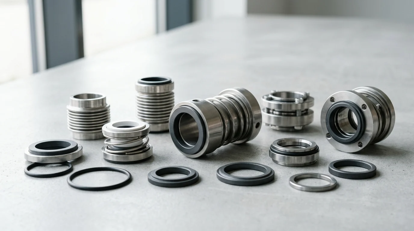
Why Strategic Mechanical Seal Selection Matters
High-speed rotating pumps, operating at shaft speeds frequently exceeding 3,600 RPM and occasionally surpassing 10,000 RPM in integrally geared configurations, present extreme dynamic challenges for fluid containment. In these rigorous applications, mechanical seals serve as the primary defensive barrier against catastrophic fluid loss, environmental contamination, and systemic equipment failure.
Selecting mechanical seals effectively requires an engineering-driven approach that scrutinizes thermodynamic limits, kinetic forces, and fluid behaviors. Strategic selection is not merely a component specification exercise; it is a foundational reliability mandate that dictates the operational viability of the entire pumping system.
How seal failures cause downtime and emissions risk
The consequences of mechanical seal failure in high-speed pump applications extend far beyond the immediate cost of a replacement component. When a seal breaches, it precipitates unplanned operational downtime that can cost tens of thousands of dollars per hour in lost production, particularly in continuous-process industries like hydrocarbon refining or chemical synthesis.
Furthermore, fugitive emissions pose severe regulatory and safety risks. Regulatory bodies mandate strict volatile organic compound (VOC) emission limits, often requiring that localized atmospheric concentrations remain below 500 parts per million (ppm). A compromised seal can instantly violate these environmental thresholds, triggering heavy fines, mandatory facility audits, and elevated safety hazards associated with toxic or highly flammable vapor clouds.
Key operating conditions for high speed pump seals
Selecting a mechanical seal for high-speed operation requires an intimate understanding of the specific kinetic and thermal environments generated within the seal chamber. As shaft speeds escalate, centrifugal forces and fluid shear rates increase exponentially, generating substantial frictional heat at the seal faces.
High-speed pumps frequently generate peripheral face velocities (tip speeds) exceeding 25 meters per second (m/s). At these velocities, fluid film vaporization becomes a critical threat; if the fluid film between the seal faces flashes into vapor, the resulting loss of lubrication will destroy the seal in minutes. Therefore, engineers must evaluate the precise suction pressure, discharge pressure, seal chamber temperature, and the specific heat capacity of the pumped fluid to ensure the seal design can dissipate heat faster than it is generated.
Failure modes that should guide early selection
Anticipating specific failure modes is a crucial step in the early stages of seal selection. In high-speed applications, engineers must proactively design against thermal distortion, dynamic tracking failure, and secondary seal extrusion.
Dynamic tracking failure occurs when the spring-loaded flexible element of the seal cannot respond quickly enough to shaft runout or vibration, leading to microscopic separation of the seal faces and subsequent leakage. This is particularly prevalent when shaft runout exceeds 0.05 mm (0.002 inches) at elevated RPMs. Additionally, thermal coning—where radial temperature gradients cause the seal faces to warp—can shift the wear track and induce localized high-pressure contact, leading to rapid blistering or heat checking of the primary ring materials. Recognizing these failure modes upfront dictates the necessity for specific seal geometries, balancing ratios, and specialized spring mechanisms.
Operating Data Required for Seal Selection
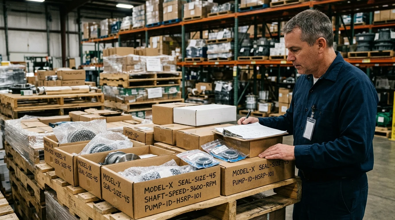
The foundation of any robust mechanical seal specification is a comprehensive and highly accurate set of operating data. Attempting to select mechanical seals based on nominal or incomplete process conditions is the leading cause of premature failure in high-speed rotating pumps.
Engineers must gather exact empirical data encompassing fluid thermodynamics, mechanical geometries, and environmental hazards to ensure the selected seal can withstand both steady-state operations and transient process upsets.
Fluid properties, pressure, and temperature
The physical and chemical properties of the pumped fluid dictate the fundamental material and configuration requirements of the seal. Engineers must document the fluid’s specific gravity, viscosity at operating temperature, and vapor pressure margin. Vapor pressure is particularly critical; the seal chamber pressure must typically be maintained at least 1.7 bar (25 psi) or 10% above the fluid’s vapor pressure to prevent flashing at the seal faces.
Temperature extremes also define the specification boundaries. Cryogenic applications, dropping to -196°C (-320°F), require distinct metallurgical choices to prevent embrittlement, whereas high-heat applications exceeding 400°C (750°F) necessitate the elimination of standard elastomers in favor of flexible graphite secondary seals.
Shaft speed, PV limits, and seal chamber geometry
Shaft speed and seal chamber geometry directly inform the physical dimensions and the permissible operating limits of the seal. The Pressure-Velocity (PV) limit is a critical calculation used to determine if a specific face material combination can survive the frictional heat generated by the application. The PV value is the product of the pressure drop across the seal faces (in MPa) and the mean sliding velocity of the faces (in m/s).
For example, a standard carbon-graphite versus ceramic seal face combination might have a maximum PV limit of 17.5 MPa·m/s, whereas a premium silicon carbide versus silicon carbide combination can withstand PV values up to 50 MPa·m/s, making the latter mandatory for high-speed, high-pressure environments. Additionally, the radial and axial dimensions of the seal chamber determine whether standard cartridge seals can be accommodated or if custom engineered solutions are required.
| Face Material Combination | Typical Max PV Limit (MPa·m/s) | Primary Application Strengths |
|---|---|---|
| Carbon Graphite vs. Ceramic | 17.5 | General water, low-speed chemicals, cost-effective |
| Carbon Graphite vs. Silicon Carbide | 35.0 | High-speed boiler feed, excellent boundary lubrication |
| Silicon Carbide vs. Tungsten Carbide | 45.0 | High-impact resistance, severe torque applications |
| Silicon Carbide vs. Silicon Carbide | 50.0+ | Abrasive slurries, extreme high-speed/high-pressure |
Process hazards, emissions limits, and dry-running risk
Process hazards and the potential for dry-running conditions must be quantified to determine the required level of redundancy and containment. Fluids that are highly toxic, carcinogenic, or spontaneously combustible upon contact with the atmosphere require stringent emissions control, typically mandating the use of dual pressurized seal arrangements.
Furthermore, engineers must evaluate the risk of dry-running—a scenario where the pump loses suction or entrains significant amounts of gas. If a high-speed pump is subjected to dry-running, the lack of a lubricating fluid film will cause conventional seal faces to shatter from thermal shock within seconds. In systems where dry-running is a known risk, the selection process must pivot toward specialized diamond-coated seal faces or the implementation of external barrier fluid systems that guarantee continuous lubrication regardless of the process fluid’s state.
How to Compare Mechanical Seal Designs
Once the operational data is meticulously documented, the selection process transitions to comparing specific mechanical seal designs and material configurations. The diversity of high-speed pump applications means that no single seal design is universally applicable.
Engineers must evaluate the structural arrangements, material metallurgy, and long-term lifecycle implications to identify the optimal configuration that balances reliability with economic feasibility.
Single, dual, tandem, balanced, and cartridge seals
The primary structural decision involves choosing between single, dual, and tandem seal arrangements, often categorized by API 682 as Arrangement 1, 2, or 3. Single seals (Arrangement 1) are utilized for benign fluids where minor leakage is acceptable. However, for high-speed pumps handling hazardous or volatile fluids, unpressurized dual seals (Arrangement 2) or pressurized dual seals (Arrangement 3) become necessary to provide a secondary containment barrier.
High-speed applications almost exclusively require balanced seals. A balanced seal is designed to reduce the hydraulic closing forces acting on the seal faces, typically achieving a balance ratio between 0.65 and 0.85. This reduction in closing force minimizes frictional heat generation, which is critical at high rotational velocities. Finally, cartridge seals—which pre-assemble the seal faces, springs, and gland plate onto a single sleeve—are heavily preferred over component seals due to their precise factory-set spring compression, which eliminates installation measurement errors.
| API 682 Arrangement | Configuration Type | Containment Capability | Typical High-Speed Application |
|---|---|---|---|
| Arrangement 1 | Single Seal | Primary seal only; no backup | Benign fluids, cooling water, non-hazardous hydrocarbons |
| Arrangement 2 | Dual Unpressurized (Tandem) | Secondary backup; collects minor leakage | Volatile organic compounds (VOCs), moderate hazard fluids |
| Arrangement 3 | Dual Pressurized (Double) | Zero process emissions; barrier fluid leaks inward | Highly toxic, lethal, or strictly regulated chemical fluids |
Face materials, elastomers, springs, and metallurgy
The selection of face materials, elastomers, and metallurgy is arguably the most critical variable in determining a seal’s operational lifespan. For primary seal faces in high-speed pumps, Silicon Carbide (SiC) and Tungsten Carbide (TC) are the premier choices due to their exceptional hardness and high thermal conductivity. A common pairing is reaction-bonded SiC against a premium carbon-graphite ring, which provides excellent boundary lubrication.
Secondary sealing elements (O-rings) must be chosen based on chemical compatibility and thermal resistance. Fluoroelastomers (FKM), such as Viton, are standard up to 200°C (392°F), but extreme chemical or thermal environments may require Perfluoroelastomers (FFKM), like Kalrez, which maintain integrity up to 327°C (620°F). The metallic components, including the springs and the cartridge gland, are typically constructed from 316 Stainless Steel, though highly corrosive environments may dictate the use of superalloys like Hastelloy C-276 or Alloy 20 to prevent stress corrosion cracking in the spring mechanisms.
Leakage, reliability, maintenance, and lifecycle cost
Evaluating mechanical seal designs requires a holistic analysis of leakage rates, reliability metrics, and total lifecycle cost (LCC). While a basic single component seal may have a lower initial procurement cost, its shorter Mean Time Between Repair (MTBR) and higher susceptibility to installation errors can result in exorbitant maintenance expenses over a 10-year operational lifecycle.
Advanced dual cartridge seals, supplemented by diamond-coated faces, require a higher initial capital expenditure but significantly reduce fugitive emissions and unplanned downtime. When performing an LCC analysis, engineers must calculate the amortized cost of the seal, the cost of the requisite barrier fluid systems, anticipated maintenance labor, and the financial risk of production outages. Often, investing in a premium, highly engineered seal configuration yields a return on investment within the first 18 months of operation by preventing a single high-speed pump failure.
Seal Support Systems and Installation Factors
A mechanical seal, regardless of its material superiority or design sophistication, cannot survive in a high-speed rotating pump without a properly engineered operating environment.
Seal support systems—commonly referred to as API piping plans—and strict adherence to installation tolerances are critical to maintaining the fluid film, controlling temperatures, and flushing away destructive particulates.
Flush, quench, barrier, buffer, cooling, and filtration plans
Seal support systems are designed to regulate the micro-environment within the seal chamber. For single seals, API Plan 11 is the most common flush plan, utilizing a high-pressure bypass from the pump discharge to flush the seal faces, remove heat, and increase chamber pressure to prevent fluid vaporization. In applications with heavy particulates, Plan 31 introduces a cyclone separator to remove solids before the flush fluid reaches the seal.
For dual pressurized seals (Arrangement 3), engineers must specify robust barrier fluid systems, such as Plan 53A, 53B, or 54. Plan 53B utilizes a bladder accumulator pre-charged with nitrogen to maintain the barrier fluid at a pressure typically 1.4 to 2.0 bar (20 to 30 psi) above the maximum seal chamber pressure. This ensures that any leakage across the inner seal faces consists of clean barrier fluid entering the process, rather than hazardous process fluid escaping into the atmosphere. Cooling systems, such as Plan 21 or Plan 23, are also frequently deployed in high-speed, high-temperature applications to actively cool the flush fluid via a heat exchanger before it interacts with the seal faces.
Installation tolerances and seal chamber conditions
The dynamic stability of a high-speed pump is heavily dependent on the mechanical tolerances achieved during installation. High rotational speeds amplify the destructive effects of misalignment and runout. To ensure seal longevity, the pump shaft must be strictly inspected prior to seal installation.
Radial shaft runout must not exceed 0.05 mm (0.002 inches) Total Indicator Reading (TIR). Axial shaft movement, or end play, must be restricted to a maximum of 0.13 mm (0.005 inches). Furthermore, the perpendicularity of the seal chamber face relative to the shaft axis is critical; it should be true to within 0.0005 mm per millimeter of shaft diameter. If these tolerances are exceeded, the flexible elements of the seal will be forced to compensate dynamically at high frequencies, leading to rapid fatigue failure of the springs or bellows and subsequent tracking failure at the seal faces.
Monitoring temperature, pressure, vibration, and leakage
Continuous monitoring of the seal and its support system is essential for transitioning from reactive maintenance to predictive reliability. High-speed pumps should be equipped with comprehensive instrumentation in accordance with API 670 standards.
Temperature monitoring is typically achieved by installing Resistance Temperature Detectors (RTDs) directly into the stationary seal gland, positioned millimeters from the seal faces. These sensors are commonly configured to trigger automated alarms if the localized temperature spikes 15°C to 20°C above the established baseline, indicating a loss of lubrication or impending face failure. Pressure transmitters on barrier fluid reservoirs (Plan 53B/C) monitor the decay rate of the barrier pressure, providing real-time data on the inner and outer seal leakage rates. Additionally, continuous vibration monitoring of the pump bearing housings provides early warning of shaft deflection or cavitation, both of which will ultimately destroy the mechanical seal if left unaddressed.
Standards, Supplier Evaluation, and Final Selection
The final phase of selecting mechanical seals for high-speed rotating pumps involves validating the engineering choices against rigorous international standards, evaluating the technical capabilities of the seal manufacturer, and executing a structured approval workflow.
This structured approach ensures that the specified seal will perform reliably under the exact conditions of the target facility and that long-term technical support is guaranteed throughout the equipment’s lifespan.
Relevant standards, documentation, and test requirements
Compliance with recognized industry standards is non-negotiable in high-speed, mission-critical pump applications. The most universally adopted standard in the hydrocarbon and chemical processing industries is API 682 (ISO 21049), now in its 4th Edition. This standard dictates stringent parameters for seal design, material selection, and testing protocols based on shaft size, temperature, and pressure.
When specifying a seal, engineers must require the manufacturer to provide comprehensive documentation, including detailed cross-sectional drawings, material certification reports (e.g., EN 10204 Type 3.1), and finite element analysis (FEA) reports verifying thermal and structural stability. Furthermore, rigorous factory acceptance testing (FAT) is mandatory. The standard typically requires dynamic testing on a specialized rig, alongside hydrostatic testing of the seal gland and pressure casings at a minimum of 1.5 times the Maximum Allowable Working Pressure (MAWP) to guarantee structural integrity before the unit is shipped.
Supplier engineering support and service capability
The complexity of high-speed mechanical seals means that the supplier must be evaluated not merely as a vendor, but as an engineering partner. A thorough supplier evaluation should focus on their in-house engineering support, computational modeling capabilities, and global service footprint. The ability of a supplier to perform computational fluid dynamics (CFD) to model fluid flow and heat transfer within the specific seal chamber geometry is highly advantageous for custom high-speed applications.
Additionally, the supplier’s service capability is critical; high-speed seals eventually require refurbishment, which demands precise lapping of the seal faces to a flatness of 1 to 2 helium light bands (0.0003 to 0.0006 mm). Engineers must verify that the supplier operates localized, certified repair facilities capable of executing these microscopic tolerances and returning the seal to its original dimensional specifications rapidly to minimize plant downtime.
Step-by-step decision workflow for final approval
To synthesize the complex data, standards, and operational requirements, engineering teams must utilize a step-by-step decision workflow for final approval. Step one involves a formal review of the process data sheet, ensuring all fluid properties, pressure transients, and thermal limits are signed off by the process engineering team.
Step two requires the mechanical reliability team to cross-reference the proposed seal arrangement and API piping plan against the pump’s physical geometry and plant utility availability, verifying that sufficient cooling water or nitrogen supply exists for the selected support plan. Step three is a rigorous commercial and lifecycle cost (LCC) review, comparing the initial capital expenditure of the seal and support system against the projected 5-year maintenance and operational costs. The final step is the generation of a formalized specification document that locks in the exact part numbers, material codes, and testing requirements, ensuring that procurement executes the purchase without unauthorized substitutions.
Key Takeaways
- Verify shaft speed, seal chamber pressure, temperature, fluid properties, and shaft runout before choosing any mechanical seal for a high-speed pump.
- Treat face velocities above 25 m/s as a critical design condition that requires heat-generation and lubrication-film analysis.
- Keep shaft runout under about 0.05 mm in high-speed service to reduce dynamic tracking failure and leakage risk.
- Select balanced seal geometries when pressure, speed, or heat load could create excessive face contact stress.
- Evaluate failure modes such as thermal coning, secondary seal extrusion, and fluid film vaporization during the early selection stage.
Frequently Asked Questions
What data is needed before selecting a mechanical seal for a high-speed pump?
Collect shaft speed, seal chamber pressure and temperature, fluid properties, suction and discharge pressures, shaft runout, vibration level, and duty cycle. These values determine face materials, balance ratio, spring design, and cooling or flush requirements.
Why are high-speed pumps harder on mechanical seals?
At speeds above 3,600 RPM, seal faces experience higher frictional heat, centrifugal forces, and fluid shear. If heat is not controlled, the lubricating film can vaporize and cause rapid face damage or leakage.
What seal face velocity should raise concern?
Peripheral face velocities above about 25 m/s require careful review of heat generation, fluid film stability, pressure balance, and cooling. At these speeds, poor seal selection can lead to thermal distortion or dry-running damage.
How does shaft runout affect seal reliability?
Excessive runout can prevent the seal faces from tracking properly. In high-speed pumps, runout above about 0.05 mm may cause face separation, leakage, vibration-related wear, and premature failure.
When should a balanced mechanical seal be considered?
A balanced seal is often preferred for higher pressure, higher speed, or heat-sensitive services because it reduces face loading. Lower face load helps control heat, extend seal life, and reduce the risk of fluid film vaporization.

Post time: Sep-09-2026