


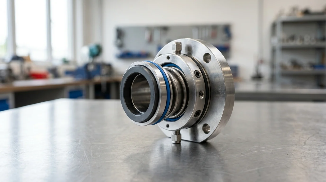
Why Specify a Cartridge Mechanical Seal to API 682
The American Petroleum Institute’s API 682 standard, currently in its 4th Edition, represents a primary global specification for mechanical seals utilized in the petroleum, natural gas, and heavy chemical industries. Designed to ensure reliability and emissions control, the standard outlines stringent engineering, testing, and documentation protocols for sealing systems. While API 682 compliance is an industry standard rather than a universal legal mandate, adhering to it is a widely accepted practice for mitigating the risks associated with volatile and hazardous fluid containment.
Central to this standard is the guideline that nearly all mechanical seals supplied for API 610 pumps should be delivered in a cartridge mechanical seal format. Unlike component seals, which require precise measurement and setting of spring compression on the pump shaft by maintenance personnel, a cartridge seal is a self-contained unit. The rotating components, stationary faces, gland plate, and sleeve are pre-assembled and preset at the factory, improving the baseline for equipment reliability in continuous-duty applications.
API 682 Duty Boundary
The API 682 standard establishes operational boundaries to ensure that a specified cartridge seal can withstand the harsh realities of hydrocarbon processing. The default design parameters cover a broad spectrum of process conditions. Standard duty boundaries outline that seals must operate reliably within a temperature range of -40°C to 400°C (-40°F to 750°F).
Pressure containment is equally defined. Category 1 and Category 2 seals are typically designed to handle dynamic sealing pressures up to 42 bar (600 psi). For high-energy applications, Category 3 seals push this boundary further, engineered to withstand dynamic pressures up to 68 bar (1000 psi). Furthermore, the standard explicitly covers shaft diameters ranging from 20 mm to 110 mm (0.75 inches to 4.3 inches), ensuring that the overwhelming majority of standard centrifugal pump dimensions fall within a pre-qualified engineering envelope.
Benefits of API 682 Cartridge Seals
A significant advantage of specifying a cartridge seal to API standards is the reduction of installation errors. In non-cartridge designs, axial setting tolerances are highly sensitive. A cartridge seal utilizes setting clips that provide a precise axial setting tolerance—often within ±0.5 mm of the optimal design point, depending on the manufacturer’s specific design. This pre-set compression ensures that the specific spring load and face balance ratio operate as qualified on the test rig.
Additionally, the cartridge design reduces maintenance downtime. A seal replacement that might take hours with a component setup can be executed more efficiently, as the unit is simply slid onto the shaft and bolted to the seal chamber. From a safety perspective, the enclosed nature of the cartridge design, combined with integrated flush and quench ports in the gland plate, provides superior management of hazardous vapors. This supports compliance with local volatile organic compound (VOC) emission limits, which in many jurisdictions restrict fugitive emissions to below 500 parts per million (ppm).
API 682 Classification Requirements
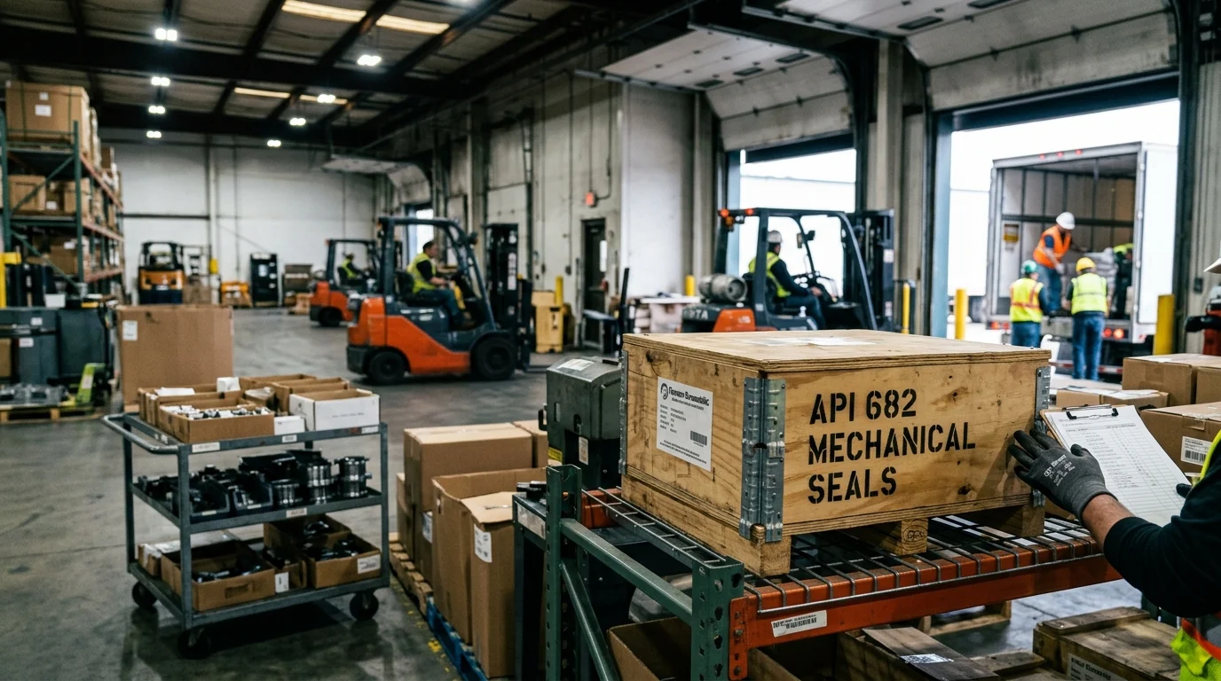
To navigate the immense variety of process conditions in petrochemical plants, API 682 utilizes a strict taxonomy for classifying a cartridge seal. This classification system ensures that pump manufacturers, seal vendors, and end-users share a common technical language when engineering a sealing solution, though interpretations of these classifications can sometimes vary by vendor and end-user specification. The classification is broken down into Categories, Types, and Arrangements, each representing a specific tier of robustness, design geometry, and redundancy.
Seal Categories, Types, and Arrangements
Categories dictate the testing and documentation rigor applied to the seal, intrinsically linked to the pump type. Category 1 seals are intended for non-API 610 pumps operating in moderate temperature and pressure environments. Category 2 seals are designed for API 610 pumps in standard refinery duties, while Category 3 seals are reserved for the most critical API 610 pump applications, requiring the most rigorous design documentation, tighter clearances, and extensive qualification testing.
Seal Types define the mechanical design of the dynamic sealing element. Type A is a balanced, inside-mounted seal utilizing O-rings as secondary sealing elements (pusher seal). Type B is an O-ring-free metal bellows seal, ideal for corrosive applications where elastomers might degrade. Type C represents a high-temperature metal bellows seal featuring flexible graphite secondary seals, necessary for applications exceeding the thermal degradation points of standard elastomers.
Materials, Seal Faces, and Elastomers
API 682 sets default material requirements to prevent galvanic corrosion and ensure dimensional stability under thermal stress. The standard dictates that gland plates and sleeves must be constructed from 316L stainless steel as a minimum baseline, while metal bellows (Type B and C) frequently require Alloy 276 or Alloy 718 for enhanced fatigue resistance. For the tribological seal faces, blister-resistant carbon graphite running against reaction-bonded or sintered silicon carbide is the default pairing, offering exceptional thermal conductivity and wear resistance.
Elastomer selection is governed by process temperature limits. Standard fluoroelastomers (FKM) are generally restricted to continuous operating temperatures of up to 200°C (390°F). When process temperatures exceed this threshold, or when aggressive chemical solvents are present, the standard necessitates the use of perfluoroelastomers (FFKM), which can maintain elasticity and chemical resistance up to 260°C (500°F). Beyond 260°C, flexible graphite replaces elastomers entirely.
Comparison of Seal Arrangements
The Arrangement of a cartridge seal defines the level of redundancy and emissions control. Arrangement 1 utilizes a single seal per cartridge. Arrangement 2 features two seals with an unpressurized buffer fluid between them, while Arrangement 3 features two seals with a pressurized barrier fluid, ensuring zero process leakage to the atmosphere.
| Arrangement | Configuration | Primary Application | Leakage Management |
|---|---|---|---|
| Arrangement 1 | Single Seal | Non-hazardous, stable fluids | Direct to atmosphere or captured via drain |
| Arrangement 2 | Dual Unpressurized | Hazardous, moderate vapor pressure | Contained in secondary seal, routed to flare/recovery |
| Arrangement 3 | Dual Pressurized | Highly toxic, zero-emissions required | Barrier fluid leaks into process, zero outward process leakage |
Selecting the correct arrangement is the primary mechanism for meeting environmental compliance. Arrangement 3 is legally mandated in many jurisdictions when handling lethal fluids like hydrogen sulfide (H2S) or highly volatile carcinogens like benzene, where the permissible exposure limit (PEL) is often 1 ppm or lower.
Design, Testing, and Documentation Requirements
Engineering a cartridge seal to API 682 standards requires adherence to dimensional constraints and rigorous physical testing. These requirements ensure that the seal will not merely fit the pump, but will survive transient operational anomalies such as shaft deflection, cavitation, and thermal shock without catastrophic failure.
Dimensional, Gland, Sleeve, and Flush Requirements
To prevent metal-to-metal contact during dynamic pump operation, API 682 mandates specific clearances. A minimum radial clearance of 3 mm (0.12 inches) must be maintained between the rotating seal components and the stationary seal chamber or gland bore. The gland plate itself must be robust enough to withstand pressure surges without warping; the standard requires a minimum gland plate thickness that can accommodate bolting of at least 12 mm (1/2 inch) in diameter.
Flush, vent, and drain ports integrated into the cartridge gland must also meet strict dimensional criteria to ensure adequate fluid flow for cooling and venting. For Category 2 and Category 3 seals, all auxiliary ports must be a minimum of 1/2-inch NPT (National Pipe Taper), whereas Category 1 seals may utilize 3/8-inch NPT ports. These dimensions are critical for integrating the seal with its required API piping plan.
Qualification and Hydrostatic Testing
Before a cartridge seal design can be marketed as API 682 compliant, it must undergo severe qualification testing. The core design must survive a dynamic qualification test on a specialized rig for a minimum of 100 hours of continuous operation, followed by simulated process upsets including loss of flush and pressure fluctuations, while maintaining a stable leakage rate well below the standard’s maximum allowable limits.
Furthermore, every individual cartridge seal must pass a static hydrostatic test before it leaves the manufacturing facility. The fully assembled cartridge gland is pressurized to 1.5 times the maximum allowable working pressure (MAWP) of the seal rating. This pressure must be held for a minimum of 30 minutes with zero visible leakage allowed. This guarantees the integrity of all static O-rings, gaskets, and structural welds prior to field installation.
Required API 682 Documentation Package
The documentation requirements for an API 682 cartridge seal, particularly for Category 3 applications, are exhaustive. A complete documentation package ensures traceability and facilitates future maintenance. This package must include detailed API data sheets specifying all operational parameters and material selections.
Suppliers are also required to provide General Arrangement (GA) drawings showing exact cross-sectional dimensions, balance ratios, and port orientations. Material traceability is enforced through the requirement of EN 10204 3.1 material certificates for all pressure-retaining components and the pump sleeve. Finally, a comprehensive installation, operation, and maintenance (IOM) manual specific to the serial number of the seal must accompany the delivery.
Specification and Sourcing Process
The specification and sourcing of an API 682 cartridge seal requires a multidisciplinary approach, bridging process engineering, rotating equipment reliability, and procurement. A successful sourcing process relies on accurate data collection and a clear understanding of how the seal interacts with external support systems.
Required Process and Pump Data
The foundation of a reliable seal specification is accurate process and pump data. Engineers must define the fluid’s specific gravity, viscosity, and most importantly, its vapor pressure at the operating temperature. To prevent dry running and face damage, the seal chamber pressure must maintain a vapor pressure margin—typically requiring the chamber pressure to be at least 50 kPa (0.5 bar) above the fluid’s vapor pressure.
Pump dynamic data is equally critical. The rotational speed, usually ranging from 1500 to 3600 RPM for standard centrifugal pumps, dictates the sliding velocity at the seal faces. High sliding velocities generate immense frictional heat, which directly influences the selection of the seal face materials and the required cooling capacity of the flush plan.
Common specification errors often occur at this stage, such as mismatching piping plans to the process fluid, or ignoring specific metallurgical requirements until late-stage procurement. Failing to account for off-design conditions or transient states during startup and shutdown can lead to misapplied seals that suffer premature failure despite being API 682 compliant on paper.
Seal Support Plans and Barrier Fluids
A cartridge seal rarely operates in isolation; it relies on an API 682 seal support system (piping plan) to regulate the environment within the seal chamber. Single seals (Arrangement 1) often utilize a Plan 11 (flush from pump discharge) or Plan 21 (cooled flush) to remove heat.
Dual seals (Arrangements 2 and 3) require external reservoirs. A standard Plan 52 (unpressurized) or Plan 53A (pressurized) system utilizes a barrier or buffer fluid reservoir. API 682 dictates the design of these reservoirs, which typically require capacities ranging from 12 liters to 20 liters (3 to 5 gallons) to ensure adequate thermal mass for heat dissipation and sufficient volume to accommodate minor fluid losses over time.
| API Piping Plan | Description | Fluid Circulation | Typical Application |
|---|---|---|---|
| Plan 11 | Flush from pump discharge | Process fluid | Clean fluids, standard heat removal |
| Plan 52 | Unpressurized external reservoir | Buffer fluid | Arrangement 2, flashing hydrocarbons |
| Plan 53A | Pressurized external reservoir | Barrier fluid (gas charged) | Arrangement 3, absolute zero emissions |
| Plan 54 | Pressurized external system | Barrier fluid (pumped) | High-energy, multi-seal installations |
Procurement Checklist for Supplier Comparison
When comparing proposals from different seal manufacturers, procurement teams should utilize a standardized checklist to ensure accurate comparisons. First, verify that the supplier holds active ISO 9001 certification and has a proven track record of manufacturing Category 2 or 3 seals. Evaluate localized service capabilities; cartridge seals require periodic factory refurbishment, making proximity to an authorized service center a logistical advantage.
Additionally, evaluate the distinction between OEM (Original Equipment Manufacturer) and aftermarket suppliers objectively. While OEM suppliers often provide extensive engineering support and guaranteed compliance with the latest iterations of the API 682 standard, many aftermarket suppliers offer fully API-compliant, cost-effective alternatives. A balanced procurement strategy acknowledges that legitimate aftermarket options can provide competitive performance and lead times, provided they meet the rigorous documentation and testing requirements of the standard.
Final Selection and Acceptance Criteria
The final selection of a cartridge seal represents a critical junction in pump engineering. The acceptance criteria must balance strict technical compliance with long-term commercial viability. A seal that meets the baseline dimensional and material requirements of API 682 must still be evaluated against the specific operational lifecycle goals of the processing facility.
Technical Bid Evaluation Criteria
Technical bid evaluation (TBE) requires scrutinizing the vendor’s proposal for any deviations from API 682 4th Edition. Engineers must review the proposed seal face balance ratio—which typically ranges from 0.75 to 0.85 for O-ring pusher seals—to ensure the closing forces are optimized for the specific pressure conditions, preventing excessive face wear or catastrophic blow-open events.
Spring loads and specific face pressures must be verified against the fluid’s lubricity. For low-lubricity fluids like light hydrocarbons, lower specific face pressures are required to prevent dry running. The TBE must also validate the thermal calculations provided by the vendor, confirming that the proposed piping plan will maintain the seal faces well below the fluid’s vaporization temperature.
Lifecycle Cost, Lead Time, and Spare Parts
While the initial capital cost of an API 682 cartridge seal is significant, it is a minor component of the Total Cost of Ownership (TCO). The primary metric for success is the Mean Time Between Failures (MTBF). API 682 design principles are structured around an aspirational MTBF target of at least 25,000 hours (approximately 3 years) of uninterrupted service, though actual performance depends heavily on operational conditions.
Lead time and spare parts availability heavily influence the final selection. Engineered Category 3 seals often command lead times of 8 to 12 weeks. Facilities must factor in the cost of holding complete spare cartridge assemblies in inventory to prevent catastrophic downtime. Vendors who offer modular cartridge designs, where common internal components are shared across different pump sizes, provide a distinct advantage in reducing spare parts inventory costs.
Final Decision Framework
The final decision framework relies on a risk matrix that weighs operational criticality, fluid toxicity, and environmental regulations. If the process fluid contains high levels of hydrogen sulfide (H2S), the seal materials must also comply with NACE MR0175 metallurgical standards to prevent sulfide stress cracking. It is important to note that NACE MR0175 compliance is separate from API 682 and represents an additional layer of specification, not an intrinsic API requirement. This additional requirement can limit vendor options to those with highly specialized metallurgical capabilities.
Ultimately, the selected cartridge seal must provide a verifiable, documented path to achieving safe operation. By adhering to the design, testing, and system integration guidelines of API 682, plant operators can finalize their selection with the confidence that the sealing system is engineered to a rigorous global standard for safety and reliability.
Key Takeaways
- Specify cartridge mechanical seals for API 610 pumps when possible because API 682 expects factory-preset seal assemblies to reduce installation variability.
- Confirm that the selected seal category matches the service pressure, with Category 1 and 2 generally rated to 42 bar and Category 3 to 68 bar.
- Check temperature suitability against the API 682 duty envelope of -40°C to 400°C before approving materials and seal support plans.
- Use setting clips and factory presetting to maintain axial setting accuracy, often within about ±0.5 mm depending on manufacturer design.
- Evaluate flush, quench, and gland port arrangements early because emissions control and hazardous vapor management are central API 682 objectives.
- Verify shaft diameter compatibility within the API 682 range of 20 mm to 110 mm before selecting a cartridge seal package.
Frequently Asked Questions
Why does API 682 prefer cartridge mechanical seals for API 610 pumps?
API 682 favors cartridge seals because they are factory-assembled and preset, reducing installation errors compared with component seals. The sleeve, gland, rotating parts, and stationary faces are supplied as one unit for more reliable field installation.
What temperature range should an API 682 cartridge mechanical seal handle?
The standard duty boundary referenced in API 682 covers approximately -40°C to 400°C (-40°F to 750°F), depending on seal category, materials, process fluid, and the selected seal support system.
What pressure limits apply to API 682 seal categories?
Category 1 and Category 2 seals are typically designed for dynamic sealing pressures up to 42 bar (600 psi). Category 3 seals are intended for higher-energy applications and may handle up to 68 bar (1000 psi).
How does a cartridge seal reduce maintenance downtime?
A cartridge seal arrives preset with setting clips, so technicians do not need to manually set spring compression on the shaft. The unit can be slid into place and bolted to the seal chamber more efficiently.
Does API 682 compliance help with emissions control?
Yes. API 682 sealing systems are designed to support reliability and fugitive-emissions control, especially in volatile or hazardous services. Integrated flush, quench, and containment features can help facilities meet VOC limits such as 500 ppm requirements.

Post time: Sep-22-2026