


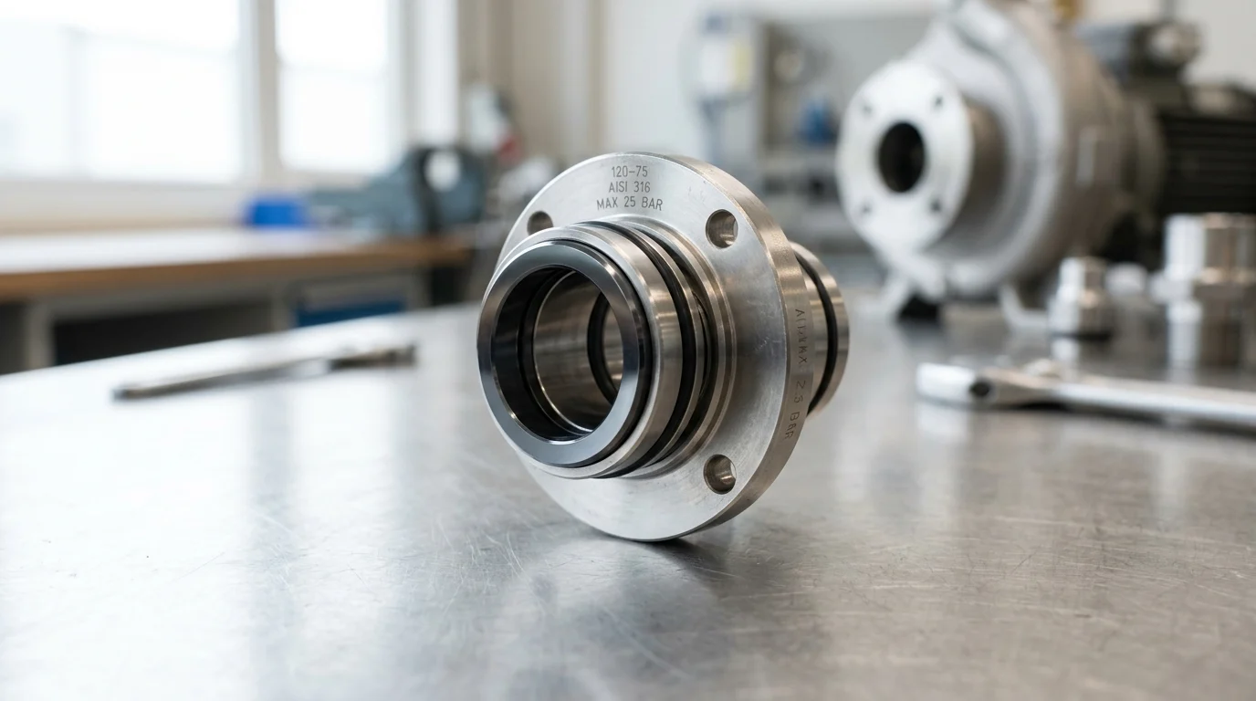
Why Mechanical Seals Are a Reliability Risk
Mechanical seals are among the most vulnerable components in centrifugal pumps, historically accounting for a majority of maintenance events in process facilities. In high-pressure applications, the operational margin for error shrinks dramatically. Seal integrity relies on maintaining a delicate balance of hydrodynamic forces that process fluctuations can easily disrupt.
When standard utility pumps scale up to high-pressure regimes, the physical demands on the sealing environment increase exponentially. Protecting continuous process systems requires a deep understanding of these fundamental vulnerabilities.
What Mechanical Seals Do in High-Pressure Pumps
A mechanical seal’s primary function is to contain fluid within a pump casing where the rotating shaft passes through the stationary housing. In high-pressure pumps—such as boiler feed pumps or pipeline injection systems—the seal must withstand extreme hydraulic forces while maintaining a dynamic lubricating fluid film between the primary seal faces.
This fluid film is extraordinarily thin, typically measuring just 1 to 3 microns. If the film becomes too thick, the pump leaks excessively past the faces. If it becomes too thin, the faces make physical contact, leading to rapid frictional wear, thermal degradation, and the ultimate destruction of the sealing interface.
How Pressure, Speed, and Temperature Increase Risk
A mechanical seal’s reliability is mathematically governed by its Pressure-Velocity (PV) limit, the product of the pressure drop across the seal faces and the sliding velocity of the rotational components. High-pressure operations frequently push seals toward PV values exceeding 100,000 psi-ft/min. This threshold is commonly cited in general-purpose applications for standard seal materials; beyond it, specialized engineered solutions are required. At these extremes, mechanical load drastically increases contact pressure.
Simultaneously, high rotational speeds generate severe frictional heat. Temperature spikes alter fluid viscosity, reducing its load-bearing capacity and pushing it closer to its vaporization point. A reduced vaporization margin can abruptly transform a stable hydrodynamic state into a high-friction boundary lubrication scenario.
How Seal Failures Drive Downtime and Repair Costs
The financial impact of a mechanical seal failure extends far beyond the cost of replacement components. In continuous process industries, seal failures are a primary driver of unplanned downtime, adversely affecting Mean Time Between Failure (MTBF) metrics and overall plant availability.
Depending on pump size, metallurgy, and industry sector, direct repair costs for a high-pressure, engineered seal cartridge can range from $5,000 to over $30,000 per incident. This includes specialized labor, replacement parts, and crane operations for large API pumps. Furthermore, secondary costs associated with lost production, environmental remediation, and collateral damage to pump bearings or shafts often eclipse direct maintenance expenditures.
Operating Conditions That Cause Seal Failure
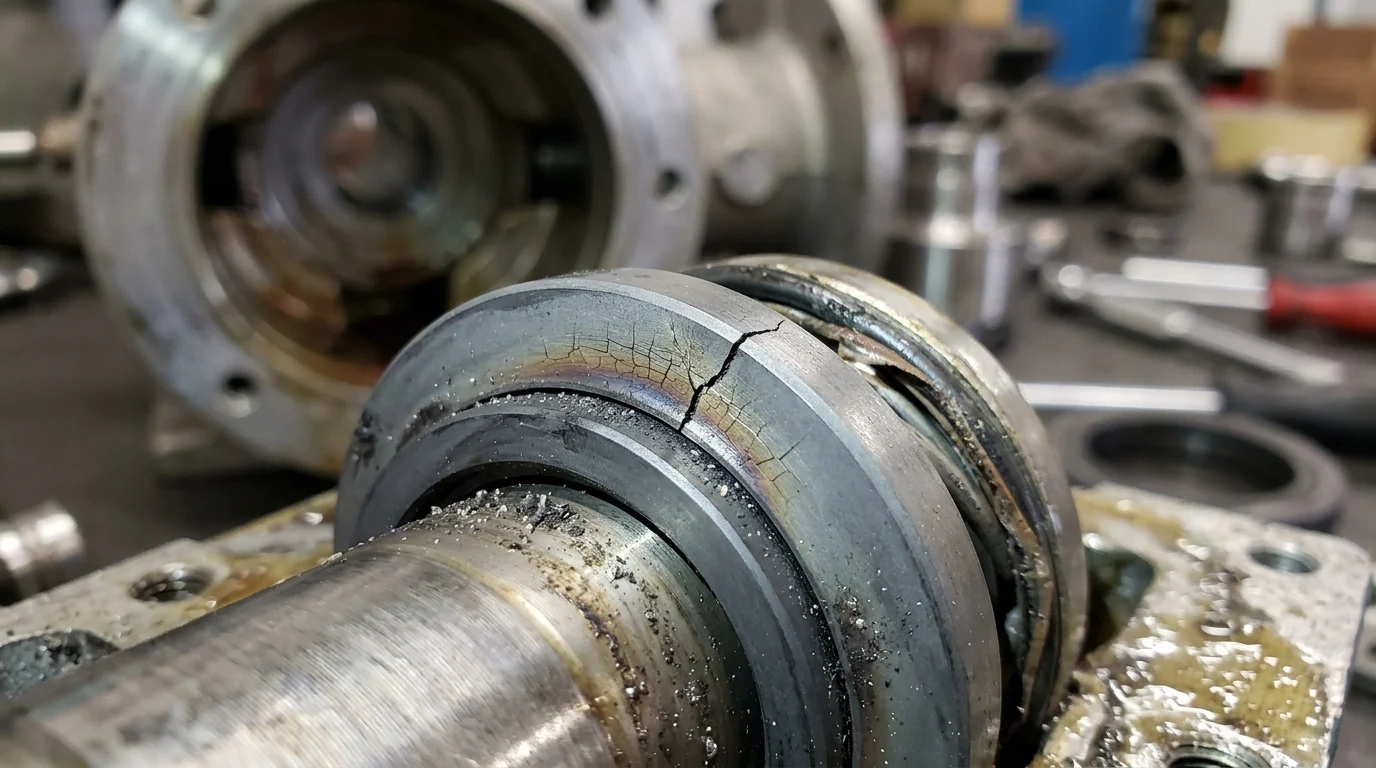
The operational environment dictates the longevity of mechanical seals. Even the most robustly engineered seal will degrade rapidly if subjected to hydraulic and thermal conditions exceeding its design parameters. Identifying these disruptive operating conditions helps pinpoint the root causes of premature seal mortality in high-pressure systems.
Pressure Spikes, Hydraulic Load, and Cavitation
Pressure spikes—often caused by water hammer or sudden valve closures—impose severe hydraulic shock loads on the seal assembly. Thermal and pressure transients during startup, coast-down, and minimum flow bypass operations also introduce critical vulnerabilities, rapidly altering the seal’s environment before steady-state conditions are reached. These transient forces can cause micro-deflection of the primary seal faces, compromising their carefully lapped flatness and allowing fluid to bypass the sealing gap.
Additionally, inadequate Net Positive Suction Head (NPSH) leads to cavitation: the formation and subsequent violent collapse of vapor bubbles within the pump casing. When these bubbles implode near the seal faces, they generate localized shockwaves with transient pressures that can exceed 10,000 psi. These microscopic impacts can pit the seal faces, shatter brittle materials like Silicon Carbide, and destroy the seal assembly’s structural integrity.
Heat Generation, Dry Running, and Vaporization
Heat generation is an unavoidable byproduct of fluid shear and localized friction at the seal faces. Effective operation requires a continuous flow of fluid to dissipate this heat. If a pump loses suction or operates against a closed discharge valve, dry running occurs. Without cooling and lubrication, face temperatures can escalate by several hundred degrees in a matter of seconds, causing severe thermal shock.
Even without total dry running, inadequate cooling can lead to localized fluid vaporization across the seal faces. To prevent this, operators must maintain a strict vapor pressure margin. A common rule of thumb for API refinery services is ensuring the stuffing box pressure remains at least 50 psi above the fluid’s vapor pressure at the maximum operating temperature. However, this margin varies significantly based on fluid type, seal design, and specific manufacturer guidelines.
Abrasive Solids, Corrosion, and Fluid Viscosity Changes
The physical and chemical properties of the pumped medium introduce additional failure vectors. Abrasive solids suspended in the fluid can penetrate the microscopic gap between the seal faces, acting as a grinding paste that rapidly erodes the lapped surfaces. Corrosive fluids attack the metallurgy of seal components—particularly springs, welded metal bellows, and drive pins—leading to a loss of mechanical face loading.
Fluctuations in fluid viscosity pose an equally severe threat. Fluids exceeding 300 centistokes (cSt) in viscosity exert immense shear stress on the seal faces and drive mechanisms. This can potentially twist bellows or shear drive pins if the pump is started while the process fluid is cold and highly viscous.
| Operating Condition | Primary Failure Mechanism | Visible Symptoms | Critical Threshold |
|---|---|---|---|
| Cavitation | Fluid implosion at seal faces | Pitting on metal parts, chipped seal faces | Typically NPSHa < NPSHr + 3 ft |
| Dry Running | Loss of lubricating fluid film | Heat checking, melted elastomers | Often < 1 micron film thickness |
| High Viscosity | Excessive shear stress | Drive pin wear, torsional shearing | Generally > 300 cSt (without hard faces) |
Mechanical Seal Design Choices for High Pressure
To counteract the destructive forces in high-pressure pumping systems, engineers must carefully select mechanical seal designs, materials, and support systems. Transitioning from standard utility pumps to high-pressure process pumps requires a fundamental shift in seal architecture to manage increased hydraulic loads and thermal outputs.
Balanced vs. Unbalanced Seal Designs
A primary design choice in high-pressure applications is the distinction between balanced and unbalanced seals. Unbalanced seals subject the entire rotating face to the full hydraulic pressure of the stuffing box, forcing the faces together under an immense load. Because of the excessive frictional heat generated, this design is generally limited to operating pressures below 150 to 200 psi.
In contrast, balanced seals feature a stepped shaft or sleeve that reduces the hydraulic area acting on the seal face. By manipulating the balance ratio—typically engineered between 0.65 and 0.85 across the industry—designers can control the closing force. This geometric modification allows balanced seals to maintain optimal lubrication and operate reliably at pressures exceeding 1,200 psi without generating destructive heat.
Seal Face Materials, Elastomers, and Metallurgy
Material selection dictates a seal’s tolerance to pressure, temperature, and chemical attack. For high-pressure primary faces, standard carbon-graphite is often replaced by Silicon Carbide (SiC) or Tungsten Carbide (TC) due to their superior hardness, high thermal conductivity, and resistance to deflection under extreme PV loads.
Secondary sealing elements, such as O-rings, are equally critical. Standard elastomers like NBR or EPDM may extrude under high pressure or degrade thermally. Fluoroelastomers (FKM) provide stability up to roughly 400°F, while Perfluoroelastomers (FFKM) are required for extreme applications, offering chemical inertness and temperature resistance up to 600°F. The metallurgy of the seal cartridge, typically 316 Stainless Steel, may also be upgraded to Duplex stainless steel or Alloy 276 to prevent stress corrosion cracking in aggressive media.
API Seal Plans, Flush Systems, and Barrier Fluids
High-pressure seals rarely operate in isolation; they depend on API (American Petroleum Institute) seal flush plans to control the stuffing box environment. A standard API Plan 11 bypass flush is often insufficient for high-pressure, high-heat applications. Instead, an API Plan 23, which recirculates fluid through a closed-loop heat exchanger, is frequently deployed to drastically reduce the fluid temperature surrounding the seal faces.
For hazardous or ultra-high-pressure media, dual pressurized balanced seals utilizing API Plan 53B (bladder accumulator) or 53C (piston accumulator) are the industry standard. These systems utilize a barrier fluid maintained at a pressure 20 to 30 psi higher than the pump’s stuffing box pressure. This ensures that any leakage across the inner seal face consists of clean barrier fluid rather than the hazardous process medium.
| API Plan | Configuration Description | Primary Benefit | Pressure Limit / Requirement |
|---|---|---|---|
| Plan 11 | Bypass from pump discharge to seal | Flushes faces, removes heat | Driven by pump discharge pressure |
| Plan 23 | Recirculation through a cooler | Significantly lowers seal temperature | Driven by thermal management needs |
| Plan 53B | Pressurized barrier fluid with accumulator | Isolates pumped fluid, zero emissions | Barrier must be 20-30 psi > stuffing box |
Diagnosing Mechanical Seal Failure
Effective diagnosis of mechanical seal health encompasses both proactive monitoring to catch degradation early and reactive forensic inspection after a failure. When a seal fails, the physical evidence left on the components provides a roadmap to the root cause. Implementing a rigorous diagnostic methodology prevents the repetition of costly failures and guides necessary modifications to pump operations or seal design.
Step-by-Step Seal Inspection Process
A step-by-step seal inspection process must begin before the pump is completely dismantled. Document the pump’s alignment, the condition of the bearings, and any evidence of pipe strain. Once the seal cartridge is removed, disassemble it in a clean environment to prevent contamination of forensic evidence.
The primary seal faces require visual inspection under magnification. An optical flat and a monochromatic light source are used to measure face flatness. A seal face in optimal condition typically shows a deflection of no more than 2 to 3 light bands. While this baseline is commonly cited for standard industrial seals, tolerance varies based on specific manufacturer specifications and face materials. Any deviation beyond this tolerance indicates severe mechanical deflection or thermal distortion during operation.
Signs of Installation, Operating, and Design Issues
Specific damage patterns on seal components reveal whether a failure stemmed from operational extremes, design flaws, or installation errors. Operational failures often manifest as thermal or mechanical stress. Radial cracks on hard faces, known as heat checking, are a definitive sign of thermal shock caused by dry running. Meanwhile, blistering on carbon faces indicates that high-viscosity fluids or localized heating caused the binder material to expand.
Conversely, installation errors typically leave distinct mechanical signatures. For example, uneven wear tracks on the seal face or chipped drive pins often point to misalignment during installation or improper bolting torque. Extrusion of secondary O-rings—where the elastomer is forced out of its gland and physically sheared—signals either a design issue (system pressure exceeding the elastomer’s durometer rating) or a hardware mismatch where the diametral clearance exceeded standard maximum allowances.
Key Monitoring Points for Seal Performance
To minimize the need for reactive inspections, proactive diagnostics rely on real-time monitoring of key performance indicators before catastrophic failure occurs. Critical monitoring points include the temperature differential between the seal flush inlet and outlet, which directly reflects the amount of frictional heat generated at the faces.
Barrier fluid pressure in dual seal arrangements must be continuously trended. A pressure drop indicates an inner seal leak, while a continuous rise may indicate a breach of the high-pressure process fluid into the barrier system. Additionally, pump vibration monitoring is essential. According to ISO 10816 standards, overall vibration levels exceeding 0.15 inches per second (in/s) RMS often point to shaft deflection, unbalance, or bearing wear, all of which directly transmit destructive radial and axial loads to the mechanical seal.
Selecting and Managing Mechanical Seals
Securing long-term reliability in high-pressure pumping systems requires a strategic approach to mechanical seal selection and lifecycle management. Rather than treating seals as disposable commodities, facilities should specify them as critical engineered assets that require precise tracking, proactive upgrading, and rigorous inventory management.
Matching Seal Design to Pump Duty and Fluid Risk
The selection process must rigorously match the seal design to the specific pump duty and the inherent risks of the pumped fluid. Engineers must evaluate the fluid’s specific gravity, vapor pressure curve, and toxicity profile against the pump’s entire operating envelope. For benign fluids at moderate pressures, a single balanced seal with hard faces may suffice.
However, if the process involves hazardous chemicals, lethal gases, or highly volatile hydrocarbons under high pressure, safety and environmental regulations mandate the use of dual unpressurized or dual pressurized seal arrangements. The exact margin between the fluid’s operating temperature and its boiling point at the seal chamber pressure dictates whether advanced cooling plans are required to maintain a stable liquid film.
When to Upgrade Seals or Support Systems
Recognizing when to upgrade a seal or its accompanying support system is a cornerstone of reliability engineering. A primary trigger for an upgrade is a facility’s MTBF tracking. If a specific pump’s seal MTBF consistently falls below typical industry benchmarks—often cited as 24 to 36 months depending on the application—the current design may be fundamentally mismatched to the operating conditions.
Upgrades are also necessitated by process changes. For example, uprating a pump to deliver higher discharge pressures may push an existing unbalanced seal beyond its safe operating limits, requiring a transition to a balanced design. Upgrading from a basic flush to a pressurized barrier system (for instance, transitioning from Plan 52 to Plan 53A) is often required when fugitive emission regulations tighten or when process fluid crystallization causes repeated inner seal face hang-ups.
Treating Mechanical Seals as Engineered Assets
Comprehensive lifecycle management and inventory optimization are essential for maximizing the value of these engineered components. Serializing seal cartridges allows operators to track repair history, failure modes, and operational lifespan across different pump assets. Standardization programs play a vital role in this management strategy. By auditing plant-wide pump populations and consolidating seal designs, facilities can often reduce their specialized seal inventory variations by 15% to 20%, depending on site complexity.
Evaluating seals through a Total Cost of Ownership (TCO) model—which factors in energy consumption from seal friction, barrier fluid usage, and downtime losses—justifies investing in high-performance technologies. Ultimately, mitigating high-pressure seal failures requires a synthesized approach: matching robust seal and flush plan designs to the specific hydraulic duty, proactively monitoring thermal and vibrational indicators, and using forensic evidence from failed seals to drive continuous improvement. By applying this decision framework, facilities can optimize pump uptime and ensure long-term operational stability.
Key Takeaways
- Maintain a stable 1 to 3 micron fluid film between seal faces because both excessive leakage and face contact can quickly destroy the sealing interface.
- Evaluate the seal’s Pressure-Velocity limit before operation, since applications approaching 100,000 psi-ft/min often require specialized materials or engineered seal designs.
- Control pressure spikes, water hammer, and sudden valve closures because hydraulic shock can overload seal faces and trigger premature failure.
- Monitor temperature rise and fluid vaporization margin, as heat reduces viscosity and can shift the seal from hydrodynamic lubrication to damaging boundary contact.
- Treat seal failures as reliability events, not just parts replacements, because direct repair costs for high-pressure engineered cartridges can exceed $30,000 per incident.
Frequently Asked Questions
What is the main reason mechanical seals fail in high-pressure pumps?
Most failures occur when pressure, speed, temperature, or process instability disrupts the thin lubricating film between seal faces, causing leakage, face contact, heat generation, and rapid wear.
How thin is the lubricating film in a mechanical seal?
The fluid film between mechanical seal faces is typically only 1 to 3 microns thick. Too much film causes leakage, while too little causes face contact and damage.
What does PV limit mean for mechanical seals?
PV limit is the product of pressure drop and sliding velocity. When high-pressure pumps approach or exceed about 100,000 psi-ft/min, standard seal materials may require engineered alternatives.
Can pressure spikes cause immediate seal damage?
Yes. Water hammer, sudden valve closures, and cavitation can create hydraulic shock that overloads seal faces, distorts components, and breaks down the lubricating film.
Why are high-pressure seal failures so expensive?
Repairing engineered seal cartridges can cost $5,000 to more than $30,000 per incident, not including lost production, environmental cleanup, or collateral pump damage.

Post time: Jul-28-2026