


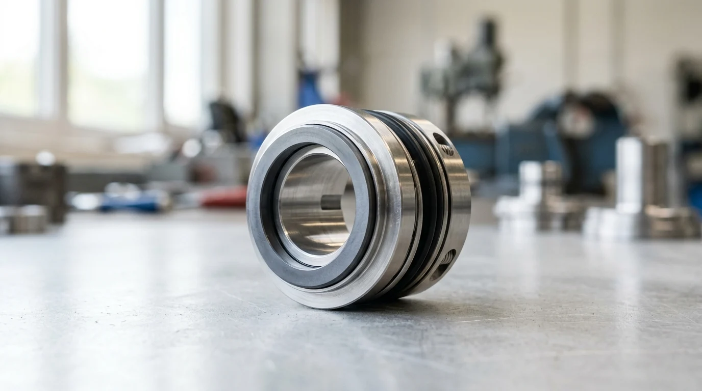
Why Mechanical Seal Spring Failures Matter in Continuous Operation
In continuous operation centrifugal pumps, the mechanical seal represents the critical barrier between the process fluid and the atmosphere. While hydraulic pressure from the pumped fluid provides the primary closing force during steady-state operation, the mechanical seal relies entirely on its spring mechanism to maintain face contact during startup, shutdown, and transient pressure events. The spring provides a constant mechanical load—typically engineered between 15 and 30 psi (1 to 2 bar)—to ensure the primary seal faces track each other precisely, compensating for shaft end-play, thermal expansion, and elastomer hysteresis.
When mechanical seal springs fail, the delicate balance of closing forces is disrupted, leading to immediate and often catastrophic loss of containment. In high-demand sectors such as hydrocarbon processing, chemical manufacturing, and power generation, where pumps operate continuously for months or years, a compromised spring mechanism translates directly to unscheduled downtime, environmental hazards, and significant financial losses. Understanding the mechanics of spring failure is essential for reliability engineers tasked with maximizing pump Mean Time Between Failures (MTBF).
Impact on Uptime, Leakage Control, and Energy Use
The immediate consequence of spring degradation is the separation of the primary seal faces. In a healthy mechanical seal, the fluid film between the rotating and stationary faces is maintained at a thickness of roughly 1 to 3 microns. If a spring loses its tension or breaks, the faces can separate beyond this tolerance. This separation causes leakage rates to escalate rapidly from acceptable fugitive emissions (often strictly regulated below 50 parts per million of volatile organic compounds) to visible, hazardous leaks.
Furthermore, seal face separation impacts the overall energy profile of the pumping system. When springs fail to compensate for misalignment or wear, the resulting uneven face loading can cause localized friction spikes. This dry running or boundary lubrication scenario increases the torque required to rotate the shaft, subtly driving up motor amperage. In severe cases, maintenance teams must deploy external flush systems, such as API Plan 32, at higher flow rates and pressures to compensate for the failing seal, further increasing the energy and water consumption of the process.
Why Spring Reliability Should Be a Maintenance Priority
Industry data consistently indicates that mechanical seal failures account for 60% to 70% of all centrifugal pump maintenance interventions. While abrasive face wear and O-ring degradation are frequently cited, spring failure acts as a critical, often underlying root cause in 10% to 15% of these events. Because the springs are typically hidden within the stuffing box or seal cartridge, their degradation goes unnoticed until the primary faces are permanently damaged.
Prioritizing spring reliability shifts maintenance strategies from reactive to proactive. By analyzing the specific failure modes of the spring mechanism—whether metallurgical, mechanical, or chemical—engineers can specify the correct spring architecture and alloy during the initial pump commissioning or seal upgrade. Ensuring that the spring component can survive the intended 36-to-60-month operational lifecycle without losing its engineered load is a fundamental requirement for achieving broader plant reliability goals.
Mechanical Seal Spring Functions and Failure Modes
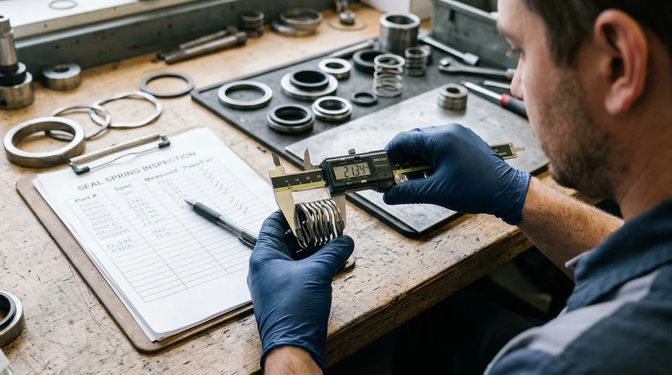
Mechanical seal springs are designed to deliver a uniform axial force that keeps the rotating and stationary faces in contact despite dynamic shaft movements. The architecture of the spring dictates how this load is distributed, how the seal accommodates axial travel, and how vulnerable the mechanism is to environmental contaminants. Recognizing the distinct functions and inherent vulnerabilities of each spring design is the first step in diagnosing premature seal failure.
How Single, Multiple, and Wave Springs Work
Single coil springs are characterized by a single, heavy-gauge wire (typically 3 to 5 mm in diameter) wrapped around the shaft. Their robust construction makes them highly resistant to corrosion and clogging from highly viscous fluids or slurries. However, single springs have a significant drawback: they apply uneven load to the seal face, often causing distortion or uneven wear at high speeds. Furthermore, their large axial footprint requires a deeper stuffing box, and they are direction-dependent, meaning they must be wound specifically for clockwise or counter-clockwise shaft rotation to prevent unwinding.
Multiple spring designs utilize several smaller springs (often with wire diameters under 2 mm) arranged radially around the seal assembly. This configuration provides an exceptionally uniform face load, minimizing face distortion and allowing for bi-directional rotation. Because they are smaller, multiple springs require significantly less axial space. However, their tight coil spacing makes them highly susceptible to clogging. If process fluids contain suspended solids larger than 100 microns, particulate matter can pack between the coils, effectively solidifying the spring and preventing axial travel.
Wave springs are manufactured from flat wire coiled into a continuous wave shape. They are engineered to deliver the same spring force as multi-spring designs while consuming up to 50% less axial space, making them ideal for compact, low-clearance stuffing boxes. Despite their spatial efficiency, wave springs offer limited axial travel and are prone to binding if the seal faces experience excessive wear or if the shaft exhibits high end-play. They are also highly sensitive to particulate buildup, which can easily lock the wave crests together.
Fatigue, Corrosion, Clogging, and Loss of Load
Fatigue is a primary mechanical failure mode, typically induced by high-cycle axial movement. If a pump shaft exhibits excessive runout (e.g., greater than 0.002 inches per inch of shaft length) or severe misalignment, the springs must constantly compress and extend with every revolution. At a standard motor speed of 3,600 RPM, this equates to over 5 million compression cycles per day, rapidly leading to metal fatigue and fracture.
Corrosion severely accelerates the likelihood of spring failure, particularly because springs are manufactured from cold-worked, high-tensile materials. Chloride stress corrosion cracking (CSCC) is a common phenomenon when standard 300-series stainless steel springs are exposed to high-chloride environments at elevated temperatures. The combination of tensile stress from the spring load and the corrosive attack causes microscopic cracks to propagate rapidly through the wire cross-section.
Clogging and loss of load represent the final major failure categories. Clogging occurs when process fluids solidify, polymerize, or deposit scale between spring coils, turning a dynamic component into a rigid block. This “hang-up” prevents the faces from closing during transient pressure drops. Loss of load, or thermal relaxation, occurs when the spring is operated above its metallurgical temperature limit. For example, a standard 304 stainless steel spring may begin to yield and lose its manufactured tension when exposed to continuous process temperatures exceeding 150°C (300°F), resulting in a permanent reduction in face closing force.
Operating Conditions That Accelerate Spring Failure
The longevity of a mechanical seal spring is inextricably linked to the environment within the pump’s stuffing box. Process conditions—ranging from extreme thermal profiles to aggressive fluid chemistry—dictate the mechanical stresses placed on the spring metallurgy. Engineers must evaluate these operating parameters comprehensively to prevent accelerated degradation of the seal’s closing mechanism.
Effects of Temperature, Pressure, Speed, and Vibration
Temperature extremes dictate the metallurgical stability of the spring. In high-temperature applications, such as boiler feed pumps or hot oil circulation exceeding 200°C (392°F), standard alloys experience thermal relaxation. The heat lowers the yield strength of the metal, causing the spring to permanently compress and lose its engineered 15 to 30 psi load. Conversely, cryogenic applications below -100°C (-148°F) can cause certain alloys to become brittle, increasing the risk of sudden fracture under dynamic load.
Pressure, speed, and vibration act as mechanical multipliers for spring fatigue. In high-pressure applications (e.g., stuffing box pressures exceeding 400 psi / 27 bar), the hydraulic forces dominate the face closing, but the springs must still withstand the intense pressure environment without buckling. High shaft speeds (exceeding 3,600 RPM) and excessive vibration (greater than 0.1 in/s RMS) force the springs to micro-adjust thousands of times per minute. This high-frequency tracking accelerates fatigue life, especially if the pump operates away from its Best Efficiency Point (BEP), inducing radial shaft deflection.
Effects of Fluid Chemistry, Solids, Crystallization, and Viscosity
Fluid chemistry and particulate content are the primary drivers of clogging and corrosion. When pumping slurries containing more than 5% solids by weight, the particulate matter will invariably migrate into the tight clearances of multiple spring assemblies. As the solids pack between the coils, the spring becomes “coil-bound,” rendering it incapable of pushing the seal face forward to compensate for wear.
Crystallization and viscosity present similar physical threats. Fluids like sodium hydroxide or sugar syrups can crystallize upon contact with atmospheric air at the seal faces. These hard crystals can tear the elastomer secondary seals and cement the springs in place. Furthermore, highly viscous fluids (exceeding 300 cSt) create significant shear resistance. The drag forces exerted by thick fluids can physically twist or deform single coil springs, altering their load profile and causing uneven face wear.
Comparison of Spring Types, Alloys, and Service Limits
Selecting the correct spring alloy is the most effective defense against aggressive operating conditions. Standard 316 Stainless Steel is sufficient for benign water and light chemical duties, but higher-grade alloys are mandatory for challenging environments. Upgrading the metallurgy increases the initial capital cost of the seal but drastically improves the MTBF by resisting both thermal relaxation and chemical attack.
The following table outlines the service limits and typical applications for common mechanical seal spring alloys:
| Spring Alloy | Max Operating Temperature | Corrosion Resistance | Typical Application / Vulnerabilities |
|---|---|---|---|
| 316 Stainless Steel | 200°C (392°F) | Moderate | General water, light hydrocarbons. Susceptible to Chloride Stress Corrosion Cracking (CSCC). |
| Alloy 20 | 250°C (482°F) | High | Sulfuric acid applications. Excellent resistance to general chemical pitting. |
| Hastelloy® C-276 | 400°C (752°F) | Excellent | Severe corrosives, high chlorides, sour gas (H2S). Highly resistant to localized corrosion. |
| Inconel® 718 | 600°C (1112°F) | Very High | High-temperature refinery applications, boiler feed. Exceptional high-temperature yield strength. |
How Maintenance Teams Diagnose and Prevent Spring Failure
Proactive diagnostics and rigorous installation protocols are essential for isolating spring issues before they cascade into complete seal failure. Maintenance teams must rely on a combination of visual leakage analysis, precision alignment checks, and condition monitoring to ensure the mechanical seal springs operate within their designed parameters.
Inspection Steps Based on Leakage Symptoms
The nature of a mechanical seal leak provides critical clues regarding the condition of the springs. A seal in optimal condition may exhibit an invisible vapor leak or a very slow weep (less than 5 drops per minute). However, if the leakage presents as a steady drip of 60 drops per minute or more, it often indicates partial spring binding or a loss of face tracking capability. The springs may be hung up by particulate, preventing them from closing the microscopic gap created by face wear.
If the pump exhibits a sudden, spraying leak, it typically points to a catastrophic loss of spring load—either due to total spring fracture, severe thermal relaxation, or a shattered seal face. During teardown and inspection, maintenance teams must measure the spring’s free length against the manufacturer’s original specifications. A free length reduction of greater than 5% indicates that the spring has yielded under temperature or stress and must be discarded.
Installation, Alignment, Flush Plan, and Lubrication Checks
Improper installation is a leading cause of premature spring fatigue. Maintenance technicians must verify that the shaft runout does not exceed 0.05 mm (0.002 inches) Total Indicator Reading (TIR) at the seal face. Excessive runout forces the springs to rapidly cycle with every rotation, guaranteeing early fatigue failure. Additionally, the axial setting of the seal cartridge must be exact; compressing the seal too far can cause the springs to become coil-bound, while under-compression results in insufficient face load.
Flush plans are the primary defense against spring clogging and corrosion. Implementing the correct API 682 flush plan is critical. For instance, an API Plan 32 injects a clean, external flush fluid into the stuffing box. To effectively keep particulate away from multiple spring assemblies, this flush must be maintained at a pressure of at least 15 to 25 psi (1 to 1.7 bar) above the maximum stuffing box pressure. Routine checks of flush flow meters, pressure gauges, and inline strainers ensure the springs remain in a clean, lubricated environment.
Condition Monitoring and Maintenance Interval Planning
Modern condition monitoring allows maintenance teams to detect the secondary effects of spring degradation before a leak occurs. Vibration analysis is highly effective; an increase in high-frequency acoustic emissions or axial vibration often indicates that the seal faces are separating or chattering due to insufficient spring load. Tracking these vibration trends allows reliability engineers to intervene before the faces are destroyed.
Maintenance interval planning should be driven by MTBF targets and fluid characteristics. For clean, lubricating fluids, a mechanical seal should comfortably exceed a 36-month MTBF. However, in crystallizing or heavy slurry applications, proactive seal replacements may be scheduled every 12 to 18 months to prevent unexpected spring hang-up. Utilizing predictive maintenance software to track these intervals ensures that seals are refurbished before the springs reach their fatigue or corrosion limits.
How Engineers Select the Right Mechanical Seal Spring Design
Designing out spring failure requires engineers to match the mechanical seal architecture precisely to the operational envelope of the pump. The selection process must account for the mechanical load requirements, the chemical aggressiveness of the process fluid, and the kinematic forces exerted on the seal components during high-speed operation.
Selection Criteria for Metallurgy, Load, and Seal Configuration
The fundamental calculation in seal selection is determining the correct spring pressure, typically engineered between 1.5 and 2.5 bar (20 to 35 psi). If the process fluid has poor lubricating qualities (such as light hydrocarbons or hot water), a lower spring load is selected to minimize frictional heat generation at the seal faces. Conversely, high-viscosity fluids require a higher spring load to punch through the thick fluid film and prevent face separation.
The configuration of the springs—whether rotating or stationary—is a critical design choice. In a rotating seal configuration, the springs spin with the shaft. At peripheral speeds exceeding 4,500 feet per minute (23 meters per second), centrifugal forces can distort rotating springs, causing them to bow outward and bind against the seal components. Furthermore, any particulate in the fluid is centrifuged directly into the rotating spring coils. For high-speed or highly contaminated applications, engineers must specify a stationary spring configuration, where the springs are housed in the non-rotating gland, isolating them from centrifugal forces and reducing clogging risks.
When to Retrofit, Upgrade, or Replace the Seal
Retrofitting or upgrading a mechanical seal is justified when the historical MTBF drops below acceptable plant standards (typically 12 months for standard pumps). If a pump utilizing a rotating multiple-spring seal suffers chronic clogging from slurries, upgrading to a stationary single-spring design or a metal bellows seal is highly recommended.
Edge-welded metal bellows seals entirely eliminate the need for traditional coil springs and dynamic O-rings. The bellows core acts as both the secondary sealing element and the spring mechanism, providing uniform face load without the tight clearances that trap solids. Upgrading to a bellows seal is often the definitive solution for high-temperature applications (up to 400°C / 752°F) or heavy particulate services where traditional springs continuously fail.
Key Takeaways for Reducing Spring Failure Risk
Mitigating mechanical seal spring failure requires a holistic approach to stuffing box management, combining optimal material selection with rigorous operational controls. Engineers must balance the spatial efficiency of multi-springs against the ruggedness of single springs, while factoring in the chemical and thermal realities of the process fluid.
| Process Condition | Recommended Spring/Seal Type | Avoid | Primary Reason |
|---|---|---|---|
| Clean, High-Speed (>4500 fpm) | Stationary Multiple Springs | Rotating Springs | Prevents centrifugal distortion and uneven face loading. |
| Heavy Slurry (>5% solids) | Single Spring or Metal Bellows | Multiple Springs | Eliminates tight clearances where particulate can pack and bind coils. |
| High Temp (>250°C / 482°F) | Inconel 718 Springs / Bellows | 316 SS Springs | Prevents thermal relaxation and loss of engineered face load. |
| Low Clearance / Short Box | Wave Springs | Single Coil Springs | Wave springs reduce required axial space by up to 50%. |
By strictly controlling shaft alignment to minimize fatigue, utilizing appropriate API flush plans to maintain a clean operating environment, and upgrading metallurgy to combat thermal and chemical degradation, facilities can drastically reduce the incidence of spring-related seal failures. Ultimately, treating the mechanical seal spring not merely as a piece of hardware, but as a highly engineered dynamic component, is essential for sustaining continuous pump operation and maximizing plant profitability.
Key Takeaways
- Mechanical seal springs provide the critical closing force during startup, shutdown, and pressure transients, typically in the 15 to 30 psi range.
- A failed spring can disrupt the 1 to 3 micron seal face fluid film, causing leakage to escalate rapidly from controlled emissions to visible loss of containment.
- Because mechanical seals account for about 60% to 70% of centrifugal pump maintenance events, spring reliability should be treated as a core uptime issue.
- Spring-related problems may underlie 10% to 15% of seal failures, so engineers should investigate metallurgy, fatigue, corrosion, and installation loading during root-cause analysis.
- Selecting the correct seal design, spring configuration, and alloy during commissioning or seal upgrades can reduce unplanned downtime in continuous-duty pumps.
Frequently Asked Questions
What role does the spring play in a mechanical seal?
The spring provides the mechanical closing force that keeps seal faces in contact during startup, shutdown, and pressure changes, typically supporting a load of about 15 to 30 psi.
Why do seal spring failures cause leakage so quickly?
A healthy seal maintains a fluid film of about 1 to 3 microns. When spring force is lost, the faces separate, allowing leakage to rise from controlled emissions to visible or hazardous leakage.
How common are mechanical seal failures in pump maintenance?
Mechanical seal failures are linked to roughly 60% to 70% of centrifugal pump maintenance interventions, with spring-related problems often acting as a hidden root cause in 10% to 15% of cases.
Can the wrong spring material reduce seal life?
Yes. Incorrect spring alloys can corrode, fatigue, or lose elasticity in aggressive fluids, high temperatures, or continuous-duty operation, leading to poor face loading and premature seal failure.
Which mechanical seal designs can help reduce spring failure risk?
The best design depends on service conditions. Options include single spring, wave spring, elastomer bellow, cartridge, and double mechanical seals, such as those supplied by Victor Seals for industrial and marine pumps.

Post time: Aug-02-2026