


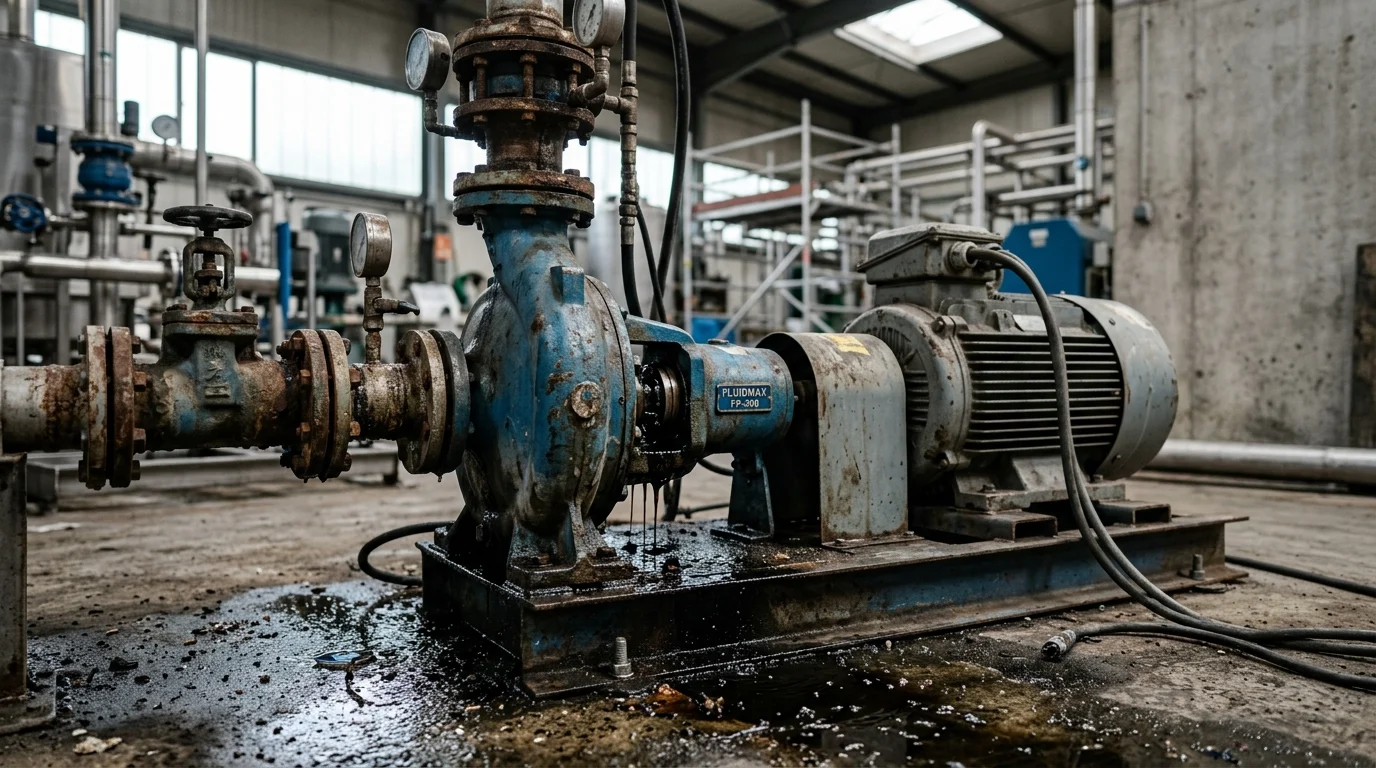
Why Do Industrial Pumps Fail from Seal Issues in Processing
In modern chemical, petrochemical, and food processing plants, rotating equipment reliability dictates overall production efficiency. Among all failure modes in rotating machinery, mechanical seal degradation remains the leading culprit behind unplanned downtime. Industry reliability studies consistently demonstrate that seal malfunctions account for approximately 65% to 70% of all centrifugal pump maintenance events. When fluid containment breaches occur, plants suffer not only from direct mechanical repair costs—typically ranging from $3,500 to $15,000 per event depending on pump size and metallurgy—but also from hazardous material leaks, environmental compliance fines, and catastrophic production halts.
Understanding the underlying causes of these failures requires a shift from reactive part replacement to proactive, root-cause reliability engineering. A processing plant operating with optimal mechanical seal environments can often achieve a Mean Time Between Failures (MTBF) exceeding 48 to 60 months, based on general industry benchmarks. Conversely, facilities plagued by chronic off-design conditions, improper installation, or misapplied seal technologies frequently see MTBF plummet to less than 6 months. To bridge this gap, reliability engineers must dissect both the mechanical architecture of the seals and the thermodynamic realities of the pumped process fluid.
How Should the Opening Frame Seal Failure as a
Framing seal failure as a symptom rather than a root cause is the first critical step in modern pump reliability programs. Mechanical seals are precision-engineered components designed to operate in highly specific, stable environments. When a seal leaks or shatters, it is rarely due to a manufacturing defect in the seal itself; rather, it is acting as a mechanical fuse that blows when system conditions exceed design thresholds. Treating the seal as a consumable wear part masks the underlying hydraulic or operational anomalies that force the component to fail prematurely.
By analyzing seal failure as an indicator of broader system distress, maintenance teams can identify issues such as inadequate suction head, piping strain, or erratic batch operations. For example, if a plant routinely replaces seals every 1,200 operating hours without investigating the fluid dynamics, they are merely resetting a timer on the next failure. Shifting the paradigm to view the seal as an intricate diagnostic tool allows operators to track variables like vibration signatures and localized heat generation, ultimately extending equipment life and reducing the frequency of unexpected breakdowns by as much as 40% over a 24-month period.
Which Seal-Related Definitions Clarify Why Industrial Pumps Fail
To effectively diagnose equipment breakdowns, technical teams must establish a standardized vocabulary regarding seal components and failure metrics. A mechanical seal primarily consists of a rotating face attached to the pump shaft and a stationary face affixed to the pump casing. The microscopic gap between these faces—typically ranging from 1 to 3 microns, with face flatness lapped to within 2 to 3 helium light bands (0.6 to 0.9 microns)—is maintained by a hydrodynamic fluid film generated by the pumped medium or an external flush fluid. If this fluid film vaporizes or becomes contaminated with abrasive particulates, the faces make direct contact, leading to rapid thermal degradation and catastrophic failure.
Equally important are the secondary sealing elements, typically composed of elastomeric O-rings or PTFE wedges, which prevent leakage along the shaft and casing. These secondary seals must maintain elasticity across the pump’s entire operating temperature range. Furthermore, environmental compliance definitions play a critical role in defining a “failure.” Under strict regulations like EPA Method 21, a pump handling Volatile Organic Compounds (VOCs) may be legally classified as “failed” if it exhibits a leakage rate exceeding 500 parts per million (ppm)—approximately 5.6 grams per hour—long before any mechanical destruction is evident. Understanding these precise thresholds is essential for aligning maintenance strategies with both mechanical integrity and environmental compliance.
Which Seal Mechanisms Explain Why Industrial Pumps Fail Prematurely
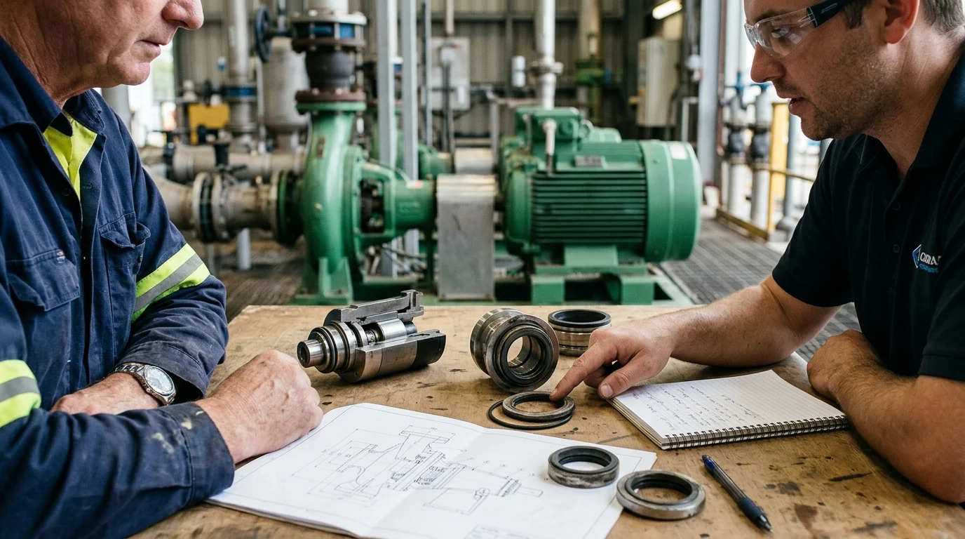
The mechanical architecture of a pump seal is a delicate balance of metallurgy, elastomer science, and fluid dynamics. Because the primary seal faces operate with tolerances narrower than a human hair, any disruption to the mechanical equilibrium rapidly accelerates wear. When these pumps fail prematurely, the root cause can frequently be traced back to the degradation of one of the specific sub-components within the seal assembly, whether through chemical attack, thermal distortion, or mechanical fatigue.
How Do Mechanical Seal Faces, Secondary Seals, Springs, and
The interaction between primary mechanical seal faces, secondary elastomers, and loading mechanisms (springs or metal bellows) forms the core of fluid containment. The primary faces, often manufactured from ultra-hard materials like Silicon Carbide (SiC) or Tungsten Carbide (TC), require continuous lubrication. If the fluid film collapses, the coefficient of friction spikes, generating localized face temperatures that can exceed 200°C within seconds. This thermal shock causes heat checking—microscopic radial cracks on the seal face—which act like cutting tools, rapidly destroying the mating surface.
Secondary seals, such as Fluoroelastomer (FKM) or Perfluoroelastomer (FFKM) O-rings, are responsible for accommodating the microscopic axial movements of the primary faces. If these elastomers undergo chemical swelling or thermal extrusion (for instance, operating an FKM O-ring beyond its typical 204°C continuous limit), they restrict the movement of the seal face, a condition known as “hang-up.” Simultaneously, the springs or bellows that provide the initial mechanical closing force (typically engineered to apply 15 to 30 psi of face pressure) can become clogged with process solids or suffer from stress corrosion cracking. When a multi-spring assembly loses tension, the seal faces separate, allowing process fluid to bypass the containment zone entirely.
When Do Packing, Single Mechanical Seals
The choice between traditional compression packing, single mechanical seals, and dual (double) mechanical seals heavily influences the failure modes a pump will experience. Compression packing, historically the standard, relies on controlled leakage (typically 40 to 60 drops per minute) to cool and lubricate the braided fibers. While highly forgiving of shaft deflection and misalignment, packing requires constant manual adjustment. When packing is overtightened to stop a leak, it burns the shaft sleeve and drastically increases the pump’s power consumption—often by 5% to 15%—ultimately leading to mechanical fatigue.
Single mechanical seals eliminate the constant leakage associated with packing but are highly vulnerable to dry running and toxic fluid releases, as they rely entirely on the process fluid for lubrication. In contrast, dual mechanical seals utilize an external barrier fluid maintained at a pressure of 15 to 30 psig above the pump’s stuffing box pressure. This ensures that if the inner seal face fails, the clean barrier fluid leaks into the process, rather than hazardous process fluid escaping to the atmosphere. Dual seals are mandatory for highly toxic, abrasive, or polymerizing fluids where a single seal would fail within days due to face contamination.
Which Comparison Table Should Link Seal Type
To systematically determine which containment strategy will prevent premature failure, reliability engineers utilize comparative performance data. The table below outlines the operational thresholds, typical failure modes, and expected lifecycles of the three primary sealing technologies used in processing plants.
| Sealing Technology | Typical Leakage Rate | Max Pressure Capacity | Typical MTBF | Primary Premature Failure Cause |
|---|---|---|---|---|
| Compression Packing | 40 – 60 drops/min | 500 psig | 6 – 12 months | Overtightening / Sleeve Wear |
| Single Mechanical Seal | < 5.6 grams/hour | 1,200 psig | 24 – 36 months | Dry Running / Thermal Shock |
| Dual (Double) Seal | Zero to Atmosphere | 3,000+ psig | 48 – 72 months | Barrier Fluid System Failure |
By analyzing this comparison, plant managers can align their seal selection with the specific process conditions. Deploying a single mechanical seal in an application requiring zero emissions will inevitably result in a compliance failure, while utilizing packing in high-pressure hydrocarbon service guarantees rapid mechanical breakdown. Proper selection based on empirical thresholds is the foundation of preventing recurring seal failures.
What Process Conditions Make Industrial Pumps Fail Due to Seal
Even the most robust mechanical seal will fail if subjected to process conditions outside its design envelope. Fluid dynamics dictate the stability of the lubricating film between the seal faces. When operational parameters deviate—whether through intentional process changes or systemic anomalies—the resulting hydraulic instability translates directly into mechanical stress. Over 40% to 50% of all instances of pump failure can be attributed directly to off-design process conditions that physically destroy the seal.
How Do Temperature, Pressure, Vapor Pressure, Viscosity, Solids
Temperature and pressure fluctuations directly alter the physical state of the fluid film at the seal faces. If the fluid temperature approaches its vapor pressure, the fluid film flashes into gas, leading to dry contact and rapid destruction. To prevent this, industry guidelines such as API 682 recommend maintaining a vapor pressure margin of at least 50 psi (or 3.5 bar) above the vapor pressure of the fluid at the operating temperature. Similarly, process viscosity impacts seal performance; highly viscous fluids (exceeding 3,000 cSt) generate excessive shear heat and can physically tear the carbon faces during startup.
The presence of suspended solids introduces a severe abrasive element to the seal environment. When slurries or crystalline fluids penetrate the microscopic gap between the seal faces, they act as a grinding compound. Solids concentrations greater than 5% by weight, or those containing particles larger than 50 microns, typically necessitate the use of dual hard faces (e.g., Silicon Carbide vs. Silicon Carbide) and an external clean flush. Without these mitigations, abrasive wear will carve deep concentric grooves into the seal faces, causing massive leakage within a few hundred operating hours.
Why Do Cavitation, Dry Running, Misalignment, Shaft Deflection
Hydraulic anomalies like cavitation occur when the available suction head drops below the required level, causing vapor bubbles to form and violently implode within the pump casing. These implosions generate high-frequency shockwaves and vibration levels that can easily exceed 0.25 inches per second RMS. This vibration shatters the brittle carbon or silicon carbide seal faces and breaks the anti-rotation pins holding the stationary face in place.
Dry running is equally catastrophic, often occurring due to operator error, closed suction valves, or vapor locking. Furthermore, mechanical misalignment and shaft deflection exacerbate these issues. If the pump and motor shafts are misaligned, or if operating away from the Best Efficiency Point causes the shaft to bend, the seal faces are forced to absorb the radial movement. Industry standards mandate that shaft deflection at the seal face must not exceed 0.002 inches (0.05 mm); any deviation beyond this rapidly fatigues the metal bellows or springs, leading to a loss of face compression and reducing L10 bearing life by as much as 50% to 70%.
How Do Cleaning Cycles, Batch Variability, Start-Stop Duty, and
In food, beverage, and pharmaceutical processing, routine operational procedures often introduce severe stress to pump seals. Clean-In-Place and Sterilize-In-Place cycles subject seals to extreme thermal shocks (often exceeding temperature gradients of 30°C per minute), rapidly shifting from ambient process temperatures to caustic chemical washes at 90°C, followed by live steam sterilization at 140°C. These rapid temperature gradients cause different seal components to expand and contract at different rates, frequently leading to O-ring extrusion or the shattering of hard faces due to thermal stress.
Batch processing variability and high start-stop duty cycles further degrade seal integrity. Every time a pump starts, it must transition from boundary lubrication (metal-to-metal contact) to full hydrodynamic lubrication. If a pump is subjected to more than 5 to 10 starts per hour, the repeated boundary friction accelerates face wear exponentially. Additionally, changing fluid parameters between batches without properly flushing the pump can lead to chemical reactions inside the seal chamber, causing polymers to cross-link and bond the seal faces together while idle, tearing them apart upon the next startup.
How Can Plants Diagnose Why Industrial Pumps Fail Before Replacing
Replacing a failed seal without diagnosing the root cause guarantees that the replacement will suffer the exact same fate, often within 30 to 90 days. A robust Root Cause Failure Analysis (RCFA) is essential to break the cycle of reactive maintenance. By treating the failed seal as forensic evidence and correlating its condition with historical operating data, maintenance teams can accurately identify the root causes of failure and implement permanent corrective actions—often turning a $3,000 diagnostic investment into $20,000+ in avoided annual downtime.
Which Inspection Steps Should Maintenance Teams Follow from Leak
The diagnostic process must begin the moment a leak is detected, before the pump is even shut down, if safely possible. Maintenance teams should first quantify the leak rate and observe the nature of the leakage—is it a steady drip, a continuous spray, or intermittent weeping? A seal that leaks only during startup but seals during steady-state operation often indicates thermal distortion of the faces, whereas a continuous, heavy leak suggests a shattered face or a completely blown O-ring.
Once the pump is locked out and the seal is extracted, visual inspection of the components is paramount. Technicians must examine the wear track on the seal faces. A normal wear track is a uniform, polished ring. A wear track that is wider than the mating face indicates severe radial shaft movement or bearing failure. If the wear track is uneven or absent in certain quadrants, it points to distortion of the gland plate, often caused by uneven tightening of the mounting bolts (exceeding the recommended torque specifications by 15% to 20%). Identifying these specific mechanical signatures helps isolate the failure mechanism from the broader symptoms.
What Operating Data Should Be Reviewed Before Blaming the
Physical inspection of the seal must be cross-referenced with quantitative operating data from the plant’s control systems. Reliability engineers should review the pressure, temperature, and flow trends during the 48 hours preceding the failure. A sudden drop in suction pressure accompanied by a spike in motor amperage often confirms an unrecorded cavitation event or a dry-running scenario caused by a blocked strainer.
Vibration analysis data is equally critical. By reviewing the vibration spectrum, analysts can differentiate between seal-induced issues and broader mechanical faults. The table below outlines key diagnostic data signatures and their probable root causes:
| Diagnostic Signature | Typical Threshold / Value | Probable Root Cause |
|---|---|---|
| Vibration Peak at 1X / 2X RPM | > 0.15 in/sec RMS | Angular or Parallel Misalignment |
| High-Frequency Random Vibration | > 5,000 Hz | Cavitation / Flow Recirculation |
| Flush Line Temp Differential | > 15°C – 20°C rise | Inadequate Flush Flow / Vaporization |
| Motor Amperage Drop | 10% – 25% below baseline | Dry Running / Loss of Suction |
For instance, high vibration peaks at exactly 1X and 2X the running speed strongly suggest angular misalignment, which would explain premature elastomeric fatigue in the seal. Conversely, random, high-frequency noise in the spectrum often corroborates cavitation or recirculation issues. Correlating a temperature spike of > 20°C in the seal flush line with a subsequent seal failure proves that the environmental control system failed to remove adequate heat, rather than the seal failing on its own.
How Should Failure Evidence Be Documented to Separate Seal
To effectively separate seal design flaws from operational abuse, failure evidence must be systematically documented using standardized taxonomy, such as ISO 14224 failure codes. Documenting the specific condition of the elastomers is highly revealing: if an O-ring is brittle and cracked, it suffered thermal degradation; if it is swollen and spongy, it experienced chemical attack; if it features a “nibbled” appearance, it was subjected to high-pressure extrusion.
Photographic evidence of the seal faces, springs, and sleeve should be logged in the plant’s maintenance management system alongside the operational data. By building a historical database of failure modes, reliability teams can identify chronic bad actors. If documentation reveals that 80% of seal failures on a specific pump involve chemical swelling of FKM elastomers, the plant can confidently justify the capital expense of upgrading to FFKM materials, thereby permanently resolving that specific failure mode.
How Should Processing Plants Prevent Industrial Pumps Fail Events Linked
Preventing the premature failure of mechanical seals requires a holistic approach that bridges the gap between engineering design, precision maintenance, and operational discipline. Facilities that transition from reactive firefighting to proactive reliability engineering often see their pump maintenance budgets decrease by 30% to 50% within 12 to 18 months. By rigorously applying strict selection criteria, enforcing precision installation standards, and utilizing data-driven decision frameworks, processing plants can drastically reduce the frequency of these failure events.
Which Seal Selection Criteria Should Guide Decisions on Material
Selecting the correct seal material and flush plan is the primary defense against process-induced failure. Material selection must account for the fluid’s extreme operating boundaries, not just its steady-state conditions. For aggressive chemical processing, utilizing Perfluoroelastomers (FFKM), which can withstand temperatures up to 327°C and resist nearly all industrial chemicals, prevents secondary seal degradation. For the primary faces, combining a Silicon Carbide rotating face with a Carbon stationary face offers excellent lubricity for clean fluids, while a SiC-on-SiC combination is mandatory for abrasive slurries.
Beyond materials, selecting the appropriate environmental control plan is critical. A basic recirculation plan (e.g., API Plan 11) from the pump discharge is sufficient for clean, cool fluids. However, if the process fluid is prone to vaporizing or polymerizing, upgrading to a pressurized barrier fluid with a bladder accumulator (API Plan 53B) or an external pressurized lubrication system (API Plan 54) isolates the seal faces from the hostile process entirely. Implementing the correct flush plan can easily extend a pump’s MTBF from a dismal 6 months to well over 36 months.
How Should Maintenance, Installation, Alignment, Lubrication
Even the most perfectly specified mechanical seal will fail rapidly if installed using archaic, imprecise maintenance practices. Precision maintenance starts with the pump shaft; technicians must use dial indicators to verify that shaft runout is strictly less than 0.002 inches and that end-play does not exceed 0.003 inches.
Key Takeaways
- Treat mechanical seal failure as a diagnostic symptom of pump system distress rather than as a simple consumable-part problem.
- Investigate suction conditions, piping strain, vibration, heat, and batch process instability before replacing a failed seal.
- Use proper seal selection and installation practices to move MTBF from chronic sub-6-month failures toward 48 to 60 months.
- Monitor seal environment variables such as temperature, pressure, vibration, and fluid contamination to detect failure risks early.
- Match mechanical seal materials and designs to the pumped fluid, operating pressure, temperature, and equipment duty cycle.
Frequently Asked Questions
How often are pump failures linked to mechanical seal problems?
Industry reliability data often attributes about 65% to 70% of centrifugal pump maintenance events to seal-related issues, making seal condition a key indicator of pump reliability in processing plants.
Is a leaking mechanical seal always the root cause of pump failure?
No. A leaking seal is often a symptom of deeper issues such as poor suction conditions, misalignment, vibration, piping strain, improper installation, or incorrect seal selection.
What operating conditions shorten mechanical seal life?
Dry running, cavitation, excessive heat, vibration, contaminated fluids, pressure excursions, and unstable batch operations can disrupt the seal face film and rapidly accelerate wear.
What MTBF should a well-managed pump seal program target?
With proper seal selection, installation, flush plans, and stable operating conditions, many processing plants can target mechanical seal MTBF of roughly 48 to 60 months.
When should a plant consider OEM or replacement mechanical seals?
Plants should consider standard, OEM, or replacement seals when upgrading reliability, matching legacy pump brands, or correcting misapplied seal designs. Victor Seals manufactures mechanical seals for industrial pumps and equipment.

Post time: Sep-07-2026