


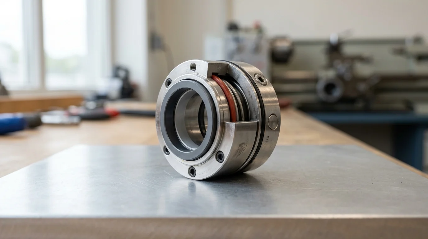
Why a New Mechanical Seal Can Fail Immediately After Installation
When a newly installed mechanical seal fails immediately upon pump startup or within the first 48 hours of operation, the event is classified as an infant mortality failure. Under standard operational paradigms aligned with API 682 guidelines, a properly specified and installed mechanical seal is expected to achieve a Mean Time Between Failures (MTBF) of at least 36 months. A reduction of this lifecycle to zero hours indicates a critical breakdown in installation protocols, system specification, or pre-commissioning procedures.
Immediate failures rarely point to natural wear and tear; rather, they serve as a diagnostic indicator of severe misalignment, dry running, or gross chemical incompatibility. Understanding the root causes of these instant failures is paramount for reliability engineers, as repeat installations without addressing the underlying systemic issue will inevitably result in identical catastrophic outcomes.
Commercial Risks of Immediate Seal Failure
The financial implications of an immediate mechanical seal failure extend far beyond the procurement cost of the replacement component. In continuous process industries such as hydrocarbon refining or chemical manufacturing, unplanned pump downtime can incur substantial production losses. When a newly commissioned pump must be taken offline immediately after a turnaround, the disruption cascades through the entire production schedule.
Furthermore, immediate seal failures often result in the sudden release of process fluids. If the pumped medium is hazardous, volatile, or toxic, facilities face strict regulatory penalties. For example, environmental regulations regarding Volatile Organic Compounds (VOCs) typically mandate strict emission limits; a seal failure that releases VOCs exceeding specific regulatory thresholds triggers mandatory reporting, immediate corrective action, and potential fines, exacerbating the commercial risk.
Why Early Leakage Should Be Taken Seriously
Treating early leakage as a minor nuisance rather than a critical system alarm is a common operational error. While minor weepage can occasionally occur during the initial break-in period of the seal faces, an immediate, steady drip or spray indicates a compromised primary sealing interface or damaged secondary elastomer. Ignoring this leakage compromises the integrity of the entire rotating assembly.
Process fluid escaping from the stuffing box at system pressures can atomize, creating explosive atmospheres or toxic vapor clouds. Additionally, process fluids leaking along the shaft will quickly penetrate the bearing housing. Contamination of bearing lubricating oil by even trace amounts of water or corrosive process fluid can significantly reduce bearing life, leading to secondary catastrophic failures of the pump internals.
What Immediate Mechanical Seal Failure Means
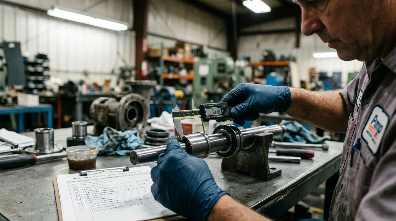
Diagnosing an immediate mechanical seal failure requires defining what actually constitutes a failure versus an expected operational state. Industry standards recognize that mechanical seals are designed to leak microscopically to maintain a fluid film between the rotating and stationary faces. However, distinguishing between normal commissioning behavior and a compromised seal boundary is the first step in effective troubleshooting.
Normal Commissioning Weepage vs. True Failure
During the initial startup of a pump, the carbon and silicon carbide (or tungsten carbide) faces of the mechanical seal undergo a brief lapping or break-in period. It is standard for a newly installed seal to exhibit minor weepage—typically defined as just a few drops per minute. This weepage should steadily decrease and cease entirely within the first 24 to 48 hours as the faces conform to one another.
Conversely, a true immediate failure presents as a continuous stream, heavy spray, or a volumetric leak rate that clearly exceeds normal break-in expectations. If the leakage does not diminish after the pump reaches its standard operating temperature, or if the volume of fluid overwhelms the drain cavity, the seal is fundamentally compromised.
| Condition | Visual Indicator | Typical Volume | Duration | Required Action |
|---|---|---|---|---|
| Normal Weepage | Occasional drops | < 20 mL/hr | < 48 hours | Monitor closely; no shutdown required |
| Marginal Leak | Steady dripping | 20 – 50 mL/hr | Continuous | Inspect flush plans; verify operating pressure |
| True Failure | Continuous stream/spray | > 50 mL/hr | Immediate | Shut down pump immediately; perform RCA |
Key Seal Components and Leak Points to Check
When inspecting a failed seal, technicians must isolate the specific leak path. A mechanical seal contains multiple potential failure points, categorized into primary and secondary sealing elements. The primary leak point is the dynamic interface between the rotating and stationary faces. If these faces are chipped, thermally distorted, or held open by particulate matter, heavy leakage will occur directly along the shaft.
Secondary leak points involve the elastomeric components, primarily O-rings or flexible wedges. Dynamic O-rings require a precise compression rate to maintain a seal while allowing the spring mechanism to advance the seal face. If an O-ring is pinched during installation, extruded due to excessive pressure, or chemically degraded, fluid will bypass the primary faces entirely. Additionally, the gland gasket—the static seal between the seal gland and the pump casing—must be inspected for improper seating or inadequate bolt torque.
Operating Conditions to Document Before Troubleshooting
Before disassembling the pump to inspect the failed seal, reliability teams must document the exact operating conditions present at the moment of failure. Post-mortem analysis is frequently hindered by a lack of baseline data. Operators should record the suction pressure, discharge pressure, and the specific gravity of the fluid at the time of startup.
Temperature differentials are particularly critical. The temperature of the process fluid entering the pump, the temperature of the seal flush fluid, and the ambient temperature of the stuffing box should be documented. A significant temperature differential between the process fluid and the expected flush temperature can indicate a lack of cooling flow, leading to immediate fluid vaporization and dry running. Furthermore, documenting the exact RPM and any recorded vibration data will help determine if severe shaft deflection contributed to the failure.
Installation Errors That Cause Early Seal Failure
Statistical analyses of rotating equipment failures indicate that human error and improper installation account for a large percentage of infant mortality cases in mechanical seals. Even highly specified, custom-engineered sealing solutions will fail instantaneously if the mechanical tolerances of the pump are not verified or if critical installation procedures are bypassed by maintenance personnel.
Incorrect Setting Length, Shaft Runout, and Pipe Strain
A mechanical seal relies on the precise dimensional stability of the pump shaft. Before any seal is installed, the shaft must be checked for runout, deflection, and end play. Industry best practices (such as API 610) mandate strict tolerances for Total Indicator Reading (TIR) regarding shaft radial runout and axial shaft end play. If a seal is installed on a shaft exceeding these tolerances, the dynamic face will be unable to track the stationary face, resulting in an immediate opening of the seal gap.
Incorrect setting length is another primary culprit in component seal failures. If the seal is set too far back, the springs will lack the tension required to keep the faces closed under dynamic fluid pressure. Conversely, if over-compressed, the fluid film is squeezed out, leading to immediate frictional destruction. Furthermore, pipe strain—caused by forcing misaligned piping flanges onto the pump nozzles—can distort the pump casing. This distortion misaligns the stuffing box relative to the shaft, causing the seal faces to run eccentrically and fail upon startup.
Dry Running, Poor Venting, and Inadequate Lubrication
Mechanical seal faces are engineered to run on a microscopic film of fluid, typically measuring in fractions of a micron in thickness. If a pump is started without properly venting the casing and the stuffing box, air or vapor becomes trapped at the seal faces. This condition, known as dry running, is catastrophic.
Without the lubricating and cooling properties of the process fluid, the friction between a rotating silicon carbide face and a stationary carbon face will generate immense heat. Face temperatures can spike rapidly during dry running. This severe thermal shock causes the faces to heat-check (develop micro-cracks), blister, or shatter entirely. Proper venting protocols, including the utilization of casing vent valves and ensuring the seal flush lines are fully primed prior to motor engagement, are non-negotiable requirements for successful commissioning.
Best Practices for Installing Cartridge Mechanical Seals
Cartridge mechanical seals were developed specifically to mitigate installation errors by pre-assembling the faces, springs, and elastomers onto a single sleeve. However, they are not immune to improper handling. One of the most frequent errors leading to immediate failure is the premature removal of the setting clips (or centering tabs). These clips maintain the precise axial and radial alignment of the seal components. They must only be removed after the gland plate is securely bolted to the pump casing and the set screws are locked onto the shaft.
Additionally, the gland plate bolts must be tightened using a crisscross pattern with a calibrated torque wrench. Uneven tightening can distort the stationary face. For standard ANSI/API pumps, gland bolt torque specifications must be strictly followed according to the manufacturer’s guidelines. Over-torquing one side of the gland can cause the stationary face to tilt by mere micrometers—enough to prevent the rotating face from establishing a parallel fluid film, resulting in immediate leakage.
Specification and Process Causes of Seal Failure
When installation errors and mechanical tolerances have been ruled out, immediate seal failures frequently point to a fundamental mismatch between the mechanical seal specification and the actual process conditions. A significant portion of early seal failures occur because the seal design, metallurgy, or environmental controls are fundamentally incompatible with the fluid dynamics present at the moment of pump startup.
Wrong Face Materials, Elastomers, or Spring Configuration
The selection of face materials and secondary elastomers must align perfectly with the chemical composition and temperature of the process fluid. If a standard Fluoroelastomer (FKM) O-ring is subjected to high-temperature hydrocarbons that exceed its thermal limits, the elastomer will undergo immediate compression set or thermal degradation, compromising the seal instantly. In such cases, high-temperature alternatives like Perfluoroelastomers (FFKM) must be specified.
Similarly, spring configurations must be matched to the fluid properties. If a multiple-coil spring seal is used in a highly viscous or particulate-laden fluid (such as crude oil bottoms or paper stock), the springs will clog instantly upon startup. The loss of spring actuation prevents the seal faces from closing, leading to a massive leak. In these applications, a single-coil spring or a stationary metal bellows configuration is required to prevent immediate fouling.
Pressure, Temperature, Vapor Pressure, and Solids Issues
Failure to maintain an adequate vapor pressure margin within the stuffing box is a primary cause of immediate seal vaporization. According to API 682 guidelines, the pressure in the seal chamber must be maintained at a sufficient margin (typically 3.4 bar / 50 psi) above the vapor pressure of the pumped fluid at the operating temperature. If the stuffing box pressure drops below this threshold during startup, the fluid film between the seal faces will instantly flash into a gas.
Vaporization violently forces the seal faces apart and causes the stationary ring to chatter. This chattering can shatter brittle silicon carbide components in a matter of seconds. Additionally, if the process fluid contains a high concentration of suspended solids or abrasives, and a hard-on-hard face combination (e.g., Silicon Carbide vs. Silicon Carbide) is not specified, the abrasive particles will immediately score softer carbon faces, creating deep grooves that allow fluid to bypass the sealing interface.
Flush Plans, Quench Systems, Barrier Fluids, and Cooling
Environmental controls, dictated by API 682 flush plans, are critical for modifying the environment immediately surrounding the seal faces. If a dual mechanical seal is installed but the barrier fluid system (e.g., API Plan 53A) is improperly pressurized, failure is imminent. The barrier fluid pressure must consistently be maintained above the maximum stuffing box pressure. If the process pressure spikes during startup and exceeds the barrier pressure, the process fluid will force the inboard seal faces open, contaminating the barrier fluid and destroying the seal.
Quench systems and cooling loops also require strict verification. An API Plan 32, which injects a clean external flush into the seal chamber, must deliver a specified flow rate to adequately cool the faces and sweep away particulates. If the flush line is valved off, undersized, or experiencing a pressure drop from the header, the seal will be starved of lubrication and fail instantaneously.
| API Plan | Function / Application | Critical Startup Metric | Immediate Failure Mode if Misapplied |
|---|---|---|---|
| Plan 11 | Recirculation from discharge to seal | Confirm continuous flow/Delta P | Orifice plugging leads to thermal shock |
| Plan 32 | Clean external flush injection | Flush pressure > Box pressure by sufficient margin | Loss of flush causes solids embedding |
| Plan 53A | Pressurized barrier fluid reservoir | Barrier pressure > Box pressure per API guidelines | Reverse pressurization blows inboard faces |
| Plan 54 | External pressurized barrier system | Flow rate maintained at specified GPM | Overheating and blistering of elastomer O-rings |
How Plants Should Diagnose and Prevent Repeat Failures
Breaking the cycle of repeat infant mortality failures requires industrial plants to adopt stringent diagnostic frameworks and quality control measures. Relying on simple part replacement without executing a formal Root Cause Analysis (RCA) guarantees that the underlying mechanical or systemic defect will destroy the subsequent seal. By implementing structured inspection and procurement protocols, reliability teams can significantly reduce repeat immediate failures.
Step-by-Step Mechanical Seal Inspection Process
When a seal fails immediately, it must be carefully extracted and subjected to a rigorous step-by-step teardown inspection. Maintenance personnel should refrain from cleaning the seal prior to inspection, as residual process fluid, localized debris, or dry powder provides critical clues. The inspection begins with the secondary seals: O-rings should be examined under magnification for signs of extrusion (indicating over-pressurization), chemical swelling, or nibbling.
Next, the primary seal faces must be analyzed. A profilometer or optical flat should be used in a controlled maintenance shop to check face flatness. Properly lapped seal faces should be flat to within 2 to 3 helium light bands (approximately 0.6 to 0.9 microns). If the faces show heavy concentric scoring, particulate contamination is the root cause. If the carbon face displays raised, blistered sections, the seal experienced violent thermal shock from dry running or vaporization during the startup sequence.
When to Reinstall, Repair, or Upgrade the Seal
Following the teardown, plant engineers must decide whether to repair the failed seal, reinstall a direct replacement, or upgrade the sealing technology. One common decision framework among plant engineers is the 60% rule: if the cost to repair the mechanical seal (including lapping faces, replacing elastomers, and testing) exceeds 60% of the cost of a brand-new unit, procurement of a new seal is economically preferable.
However, if the failure analysis reveals that the original seal specification was fundamentally flawed for the process conditions, neither repair nor direct replacement is viable. For example, if a component seal repeatedly fails due to installation errors by rotating shifts of maintenance personnel, upgrading to a fully unitized cartridge seal is the most effective corrective action. If the failure was due to uncontrollable pressure spikes in a single seal arrangement, upgrading to a dual pressurized seal system (API Plan 53 or 54) is necessary to isolate the seal faces from process volatility.
Procurement, Storage, and Installation Controls
Finally, preventing immediate seal failures begins long before the pump is taken offline; it requires strict inventory management and pre-installation controls. Elastomeric components within mechanical seals are sensitive to degradation over time. While standards like SAE ARP5316 provide eligibility codes and general guidelines for the shelf life of polymers like Nitrile (NBR) and Fluoroelastomers (FKM), these lifespans vary by polymer grade and are only valid if stored in controlled environments.
Mechanical seals must be stored in environments with temperatures maintained below 25°C (77°F) and relative humidity kept strictly under 65%. Exposure to direct ultraviolet light, ozone generated by nearby electrical motors, or extreme temperature fluctuations will cause the elastomers to become brittle while sitting on the shelf. When a degraded seal is finally installed, the hardened O-rings cannot compress to establish a seal, resulting in a leak the moment the pump is flooded. Implementing First-In, First-Out (FIFO) inventory controls and climate-controlled storage is a foundational requirement for preventing the immediate failure of newly installed mechanical seals.
Key Takeaways
- Treat seal failure within startup or the first 48 hours as an infant mortality event that requires root-cause analysis before reinstalling another seal.
- A properly specified and installed mechanical seal should often deliver an MTBF of about 36 months, so zero-hour failure points to a severe system or installation problem.
- Do not ignore steady dripping or spraying after commissioning, because leaking process fluid can contaminate bearings, create vapor hazards, and trigger regulatory exposure.
- Verify seal chamber venting, flush flow, alignment, installation dimensions, and material compatibility before startup to reduce the risk of dry running and face damage.
- Stop the pump immediately when abnormal leakage appears, because repeated restarts can turn a correctable installation issue into pump, bearing, and environmental damage.
Frequently Asked Questions
What is an infant mortality failure in a mechanical seal?
It is a failure that occurs at startup or within the first 48 hours. For a correctly specified and installed seal, this usually indicates installation error, dry running, misalignment, contamination, or incompatibility—not normal wear.
Is slight leakage normal after installing a new mechanical seal?
A very small amount of commissioning weepage may occur while seal faces establish a fluid film. A steady drip, spray, or rapid leakage is not normal and should be treated as a failure alarm.
Why can a new mechanical seal fail immediately on pump startup?
Common causes include running the seal dry, incorrect installation length, damaged elastomers, poor shaft alignment, wrong seal material, clogged flush lines, or trapped air in the seal chamber.
How long should a properly installed mechanical seal last?
Under standard operating conditions aligned with API 682 expectations, a properly specified and installed mechanical seal is often expected to achieve an MTBF of around 36 months or more.
Should I restart the pump if the new seal leaks immediately?
No. Repeated restarts can worsen face damage, contaminate bearings, and release hazardous fluids. Stop the pump, isolate it safely, and inspect installation, lubrication, alignment, and operating conditions.

Post time: Jul-18-2026