


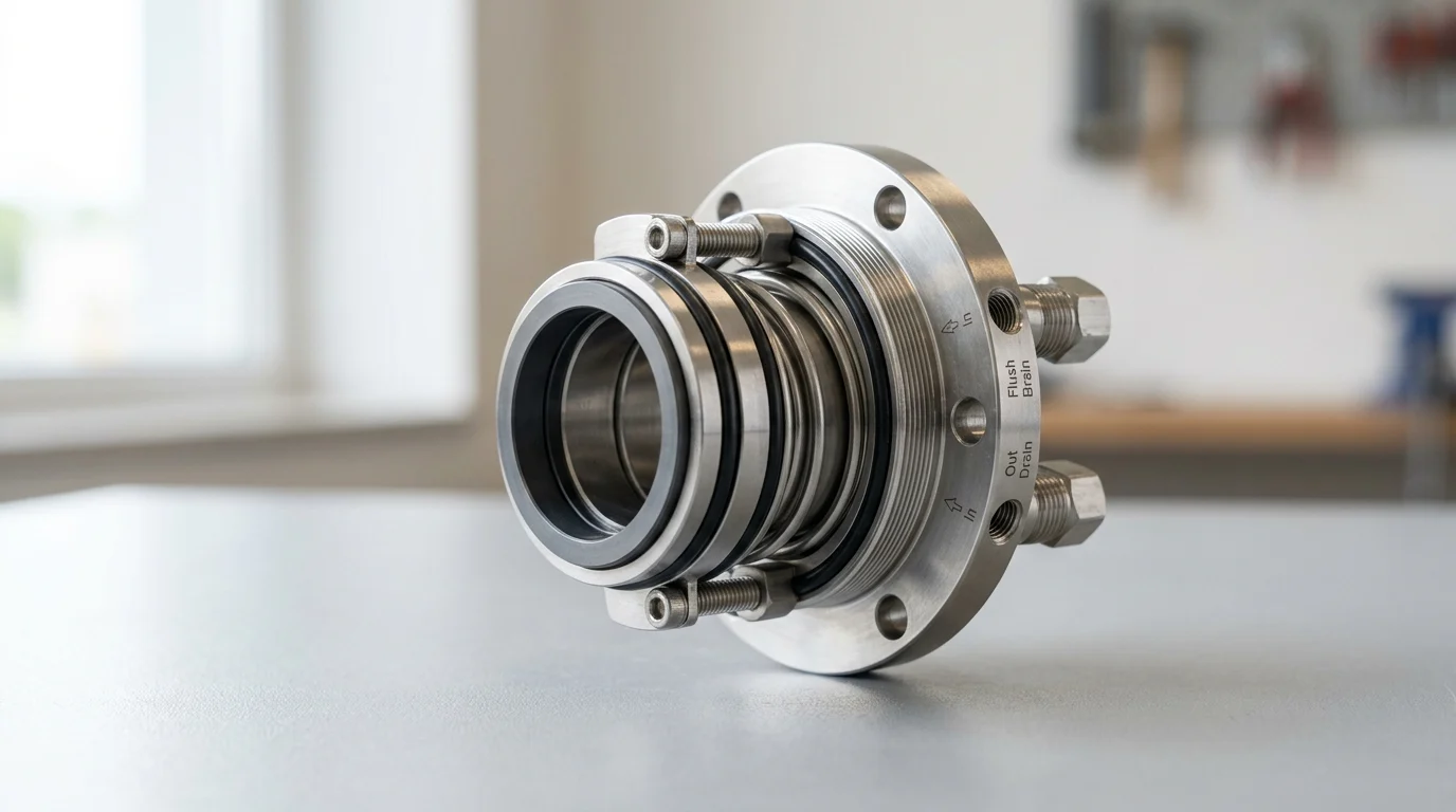
Why Seal Selection Is Strategic
In the continuous processing and hydrocarbon industries, the containment of process fluids within centrifugal pumps represents a critical engineering challenge. The transition from traditional compression packing to advanced mechanical seals has drastically reduced fugitive emissions and improved mean time between repairs (MTBR). However, selecting the appropriate sealing technology remains a complex undertaking that dictates both operational viability and regulatory compliance. Industry reliability studies consistently indicate that mechanical seal failures account for approximately 69% of all centrifugal pump failures, making seal selection the most consequential factor in pump lifecycle management.
Choosing between a single and a double mechanical seal requires a rigorous evaluation of the process fluid’s thermodynamic properties, the pump’s operating envelope, and the facility’s environmental constraints. A sub-optimal selection can result in catastrophic loss of primary containment, leading to unplanned downtime, severe environmental penalties, and unacceptable safety risks to plant personnel. Consequently, rotating equipment engineers must approach seal selection not merely as a component specification, but as a strategic risk mitigation exercise.
Impact on Uptime and Leakage Control
The direct correlation between mechanical seal design and pump uptime cannot be overstated. Mechanical seals operate on the principle of maintaining a microscopically thin fluid film between a stationary and a rotating face. When this fluid film is stable, the seal operates with minimal wear, allowing facilities to target the American Petroleum Institute (API) 682 standard expectation of 25,000 hours of continuous operation without requiring replacement.
Leakage control is the primary metric by which seal performance is judged. While all mechanical seals require some degree of fluid migration across the faces to provide lubrication, the architectural differences between single and dual configurations dictate whether this leakage enters the atmosphere or is captured within a closed-loop system. Unplanned downtime driven by excessive leakage directly impacts production yields, with high-capacity process pumps often costing facilities tens of thousands of dollars per hour in lost revenue when taken offline for premature seal replacement.
Pump Services That Drive Seal Choice
The inherent characteristics of the pumped medium—often referred to as the pump service—serve as the foundational criteria for seal selection. Services are generally categorized by their lubricity, vapor pressure, viscosity, and presence of suspended solids. Fluids with high specific gravity and excellent lubricity, such as heavy fuel oils or cool water, provide ideal environments for maintaining the critical fluid film between seal faces.
Conversely, severe services introduce thermodynamic and mechanical challenges that force engineers to upgrade seal configurations. For example, pumping light hydrocarbons with a specific gravity below 0.5 or fluids near their boiling points severely compromises face lubrication, risking vaporization across the seal faces. When a fluid vaporizes prematurely, the seal faces lose their lubricating film, leading to dry running, rapid heat generation, and thermocracking of the carbon or silicon carbide materials. Understanding the precise vapor pressure margin—the difference between the stuffing box pressure and the fluid’s vapor pressure at operating temperature—is essential for determining whether the service can sustain a single seal or if it mandates the advanced environmental controls provided by a double mechanical seal.
Single vs Double Mechanical Seal Basics
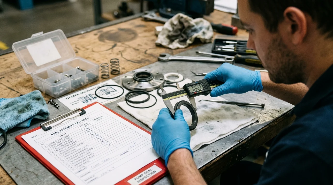
To evaluate the applicability of different sealing strategies, one must first deconstruct their mechanical architectures. All mechanical seals function by utilizing a spring-loaded or bellows-loaded rotating face pressed against a stationary face. The operational success of this interface relies on achieving a face clearance that is typically maintained between 1 to 5 microns (0.00004 to 0.0002 inches). This microscopic gap must be large enough to admit a lubricating fluid film but narrow enough to restrict volumetric leakage.
The primary divergence in seal technology lies in the number of these sealing interfaces and how the environment surrounding them is managed. This distinction dictates the hardware complexity, the footprint within the pump’s stuffing box, and the necessity for external auxiliary support systems.
How Single Mechanical Seals Control Leakage
A single mechanical seal consists of exactly one set of mating faces: one rotating with the pump shaft and one stationary in the pump gland. In this configuration, the process fluid itself is utilized as the lubricant for the seal faces. Because the fluid must migrate across the faces to prevent dry friction, a single seal inherently permits a microscopic amount of the process fluid to escape to the atmospheric side of the pump.
In benign applications, such as cooling water or non-hazardous lubricating oils, this weeping is negligible. The fluid either evaporates upon reaching the atmosphere or is collected in a minor drip pan. Single seals are highly favored for their mechanical simplicity, lower initial capital expenditure, and minimal spatial requirements within standard pump housings. However, their reliance on the process fluid for lubrication means they are entirely vulnerable to process upsets, such as cavitation, loss of suction, or sudden temperature spikes.
How Double Mechanical Seals Work
A double mechanical seal, often referred to in modern API 682 nomenclature as a dual seal, utilizes two independent sets of sealing faces within a single assembly. This architecture creates an isolated intermediate chamber between the process fluid and the atmosphere. The two sets of faces can be arranged in several geometries, including back-to-back, face-to-face, or in series (tandem).
The primary advantage of the double mechanical seal is its ability to completely isolate the process fluid from the atmosphere. By introducing an external fluid into the intermediate cavity, the seal faces are no longer solely reliant on the pumped medium for lubrication and cooling. This structural redundancy ensures that even if the primary (inboard) seal fails, the secondary (outboard) seal contains the fluid, preventing a hazardous release and allowing operators a safe window to shut down the equipment.
Barrier Fluid, Buffer Fluid, and Seal Support Systems
The intermediate fluid introduced into a double mechanical seal is classified as either a buffer fluid or a barrier fluid, depending entirely on its pressure relative to the pump’s stuffing box. A buffer fluid is maintained at a pressure lower than the process pressure (typically utilizing an API Plan 52 support system). In this tandem arrangement, the inboard seal is lubricated by the process fluid, and any leakage across the inboard faces is captured by the unpressurized buffer fluid, which sweeps it into a reservoir for safe disposal or flaring.
Conversely, a barrier fluid is maintained at a pressure higher than the process pressure—typically 1.5 to 2.0 bar (22 to 29 psi) above the maximum dynamic stuffing box pressure. Managed via API Plan 53 (A, B, or C) or Plan 54 systems, the pressurized barrier fluid forces its way across the inboard seal faces into the process. This guarantees that the process fluid never breaches the seal chamber. The selection of the barrier or buffer fluid is critical; it must be chemically compatible with the process fluid, possess excellent lubricity, and exhibit high thermal stability to absorb and dissipate the shear heat generated by two sets of rotating faces.
| Feature | Single Mechanical Seal | Double Mechanical Seal (Pressurized) | Double Mechanical Seal (Unpressurized) |
|---|---|---|---|
| Face Sets | One | Two | Two |
| Lubrication Source | Process fluid | External barrier fluid | Process fluid (inboard) / Buffer fluid (outboard) |
| Cavity Pressure | N/A | 1.5 to 2.0 bar > Process Pressure | Atmospheric / < Process Pressure |
| Leakage Direction | Process to Atmosphere | Barrier to Process & Atmosphere | Process to Buffer fluid |
| Support System | Plan 11, 13, 21, 32 | Plan 53A/B/C, 54 | Plan 52 |
Performance Comparison Criteria
Selecting between a single and a double mechanical seal requires quantifying the operational limits of each configuration against the demands of the process. Engineers must evaluate performance criteria across a spectrum of mechanical, chemical, and thermodynamic variables. While a single seal might successfully handle fluids up to 204°C (400°F) with an appropriate flush plan, extreme exothermics, aggressive corrosives, or strict emission mandates will inevitably shift the performance requirements toward dual sealing technologies.
Leakage Control, Safety, and Reliability
In evaluating leakage control, the distinction between single and double configurations is stark. A well-maintained single mechanical seal operating under optimal conditions might leak between 5 to 10 parts per million (ppm) of volatile organic compounds (VOCs) into the immediate atmosphere. While this is mechanically acceptable for the seal’s survival, it may violate stringent plant safety protocols if the fluid is hazardous.
A double mechanical seal utilizing a pressurized barrier fluid offers essentially zero emissions of the process fluid to the atmosphere. Because the barrier fluid is at a higher pressure than the pump stuffing box, the differential pressure ensures that any fluid migration across the inboard faces consists strictly of barrier fluid entering the process stream. This absolute containment provides the highest level of reliability and safety, drastically reducing the risk of fire, explosion, or operator exposure in the event of an inboard seal failure.
Fluid Toxicity, Volatility, and Corrosiveness
The chemical nature of the fluid heavily dictates the required seal architecture. Highly toxic fluids, carcinogens, and severe corrosives pose unacceptable risks if allowed to weep across a single seal face. Furthermore, fluids with high volatility—such as liquid propane, butane, or anhydrous ammonia—present a unique mechanical challenge. Because these fluids vaporize rapidly at atmospheric pressure, a single seal will experience localized flashing between the faces, destroying the fluid film and leading to catastrophic dry-running failure.
In highly corrosive services, the metallurgy of the seal components must be upgraded to exotic alloys like Hastelloy C-276 or Titanium. However, utilizing a double mechanical seal with a clean, non-corrosive barrier fluid allows the outboard seal components to be manufactured from standard 316 stainless steel, as they are never exposed to the aggressive process medium. This isolation strategy not only protects personnel from toxic exposure but also extends the MTBR by shielding critical seal components from chemical attack.
Pressure, Speed, and Dry-Running Risk
Mechanical seals are subject to severe dynamic forces, with surface speeds at the seal faces frequently reaching up to 25 meters per second (5,000 feet per minute). At these velocities, heat generation is substantial. Single seals rely entirely on the process fluid’s ability to absorb this shear heat. If the pump experiences a transient loss of suction, the resulting dry-running condition can cause the faces of a single seal to shatter from thermal shock within minutes.
A double mechanical seal mitigates the risk of dry running through its dedicated support system. If the pump loses primary suction, the pressurized barrier fluid continues to circulate, lubricating and cooling both the inboard and outboard seal faces. This thermal resilience allows the pump to survive process upsets that would otherwise destroy a single seal. However, this performance comes with a trade-off: dual seals must dissipate the heat generated by two sets of faces, necessitating larger heat exchangers in the API seal support systems to maintain the barrier fluid within its optimal temperature range (typically below 60°C or 140°F).
| Performance Criterion | Single Seal Capability | Double Seal Capability (Pressurized) |
|---|---|---|
| Fugitive Emissions | Trace amounts (5-10+ ppm) | Zero process emissions (0 ppm) |
| Dry-Running Tolerance | Extremely poor (< 2 minutes) | Excellent (sustained by barrier fluid) |
| Flashing Fluid Handling | Poor (high risk of face damage) | Excellent (isolated from atmosphere) |
| Abrasive Slurry Handling | Moderate (requires external flush) | High (barrier fluid prevents ingress) |
| Parasitic Heat Load | Base level (1x face friction) | High (2x face friction) |
When Double Mechanical Seals Are Required
While mechanical and thermodynamic properties provide the technical basis for seal selection, regulatory mandates and corporate Environmental, Health, and Safety (EHS) policies frequently override basic engineering preferences. In modern hydrocarbon processing, petrochemical manufacturing, and pharmaceutical production, the decision to mandate a double mechanical seal is often dictated by statutory requirements designed to eliminate fugitive emissions and protect the surrounding ecosystem.
Regulations and Site Standards
Environmental protection agencies worldwide enforce strict limitations on the volume of hazardous air pollutants (HAPs) and VOCs that industrial facilities can emit. In the United States, the Environmental Protection Agency (EPA) utilizes Method 21 to define and monitor leak thresholds. For many regulated services, a leak definition threshold of 500 parts per million by volume (ppmv) is strictly enforced. Equipment found leaking above this threshold triggers mandatory, time-sensitive repair protocols and potential regulatory fines.
To guarantee compliance with such stringent thresholds, plant engineers default to API 682 Category 2 and Category 3 dual seal arrangements. The Clean Air Act and subsequent Maximum Achievable Control Technology (MACT) standards explicitly require dual mechanical seals with closed-loop barrier systems for specific chemical streams. In these regulatory environments, the capital cost of a double mechanical seal is negligible compared to the financial and legal liabilities associated with non-compliance.
Hazardous, Flammable, and Toxic Services
Beyond environmental regulations, the immediate safety of plant personnel dictates the use of double mechanical seals in hazardous services. Lethal fluids, such as hydrogen sulfide (H2S), hydrofluoric acid (HF), and highly concentrated sodium cyanide, pose immediate threats to life upon exposure. For these services, a single seal is fundamentally disqualified due to its inherent weeping characteristics.
Similarly, highly flammable and auto-igniting fluids require the absolute containment provided by dual seals. When pumping fluids that operate above their auto-ignition temperature, any leakage to the oxygen-rich atmosphere will result in immediate combustion. A double mechanical seal utilizing an inert barrier fluid, such as a specialized synthetic oil or pressurized nitrogen gas (in the case of dual gas seals), isolates the volatile process fluid from atmospheric oxygen, thereby breaking the fire triangle and ensuring operational safety.
Documentation, Testing, and Compliance Checks
The deployment of double mechanical seals in critical services necessitates rigorous documentation and compliance verification before the equipment ever reaches the field. Manufacturers are required to subject these assemblies to hydrostatic testing at a minimum of 1.5 times the maximum allowable working pressure (MAWP) to certify the integrity of the pressure boundaries.
Furthermore, under API 682 guidelines, seal designs must undergo standardized qualification testing, which includes a minimum of 100 hours of dynamic testing under simulated process conditions, followed by static pressure tests. Facilities purchasing double mechanical seals for compliance-driven applications must retain these material test reports (MTRs), hydro-test certificates, and dynamic qualification logs to satisfy insurance auditors and regulatory inspectors. This heavy documentation burden reflects the critical safety function that dual seals perform in the modern industrial landscape.
Selection Workflow and Cost Evaluation
Translating fluid properties, thermodynamic limits, and regulatory constraints into a final procurement decision requires a structured engineering workflow. The selection between a single and a double mechanical seal is rarely a binary choice based on a single variable; rather, it is a multi-dimensional evaluation of risk versus lifecycle cost. A comprehensive total cost of ownership (TCO) analysis frequently reveals that the cheapest initial option may become the most expensive over a 20-year pump lifecycle.
Step-by-Step Seal Selection Process
The step-by-step seal selection process begins with an exhaustive definition of the process fluid conditions, including minimum, normal, and maximum operating temperatures, pressures, and specific gravities. Once the fluid profile is established, engineers must cross-reference the service against local and federal environmental regulations. If the fluid is classified as a hazardous air pollutant or a lethal service, the workflow immediately diverts to specifying a double mechanical seal.
If regulations do not mandate a dual seal, the process moves to a mechanical evaluation. The engineer calculates the vapor pressure margin at the seal faces. If the margin is insufficient to prevent flashing, or if the fluid contains highly abrasive particulates that cannot be managed with a simple Plan 32 external flush, a double seal is selected to provide a clean, stable lubricating environment. Finally, if a dual seal is chosen, the engineer must size and select the appropriate API support system (Plan 52, 53, or 54) based on available plant utilities and thermal load calculations.
Total Cost of Ownership Factors
The Total Cost of Ownership for mechanical seals encompasses capital expenditure (CAPEX), operational expenditure (OPEX), and risk-adjusted downtime costs. The initial CAPEX of a double mechanical seal, combined with a pressurized API Plan 53B accumulator system, can easily represent a 3x to 5x cost multiplier compared to a standard single seal with a basic Plan 11 bypass flush. This upfront investment often requires specific budgetary justification during the project engineering phase.
However, the OPEX profile shifts the financial narrative. Double mechanical seals introduce parasitic energy losses; the barrier fluid system can impose a 0.5 to 2.0 kW parasitic load on the pump motor due to the fluid shear of the secondary seal faces. Additionally, dual systems require ongoing utility support, including cooling water for the heat exchangers, nitrogen gas for accumulator charging, and periodic barrier fluid top-offs. Conversely, if a single seal is applied in a marginal service, its OPEX will be dominated by frequent replacement costs, labor for pump teardowns, and the severe financial penalties of unplanned production outages.
Final Decision Framework
The final decision framework relies on a risk matrix approach that balances initial capital outlay against MTBR and environmental liability. For benign utilities like boiler feed water or mild solvents, the single mechanical seal remains the undisputed standard, offering the highest return on investment through mechanical simplicity and low maintenance overhead.
For severe, toxic, or highly volatile services, the double mechanical seal is not merely an upgrade; it is an operational necessity. By isolating the process fluid, providing redundant safety boundaries, and guaranteeing face lubrication during transient upsets, dual seals insure the facility against catastrophic failures. Ultimately, rotating equipment engineers must weigh the immediate procurement costs against the long-term strategic imperatives of plant safety, regulatory compliance, and uninterrupted process reliability.
Key Takeaways
- Treat mechanical seal selection as a risk-control decision because seal failures account for about 69% of centrifugal pump failures.
- Select double mechanical seals when process leakage could create safety, environmental, regulatory, or production risks.
- Use single mechanical seals mainly for clean, non-hazardous, well-lubricating services where controlled leakage is acceptable.
- Evaluate vapor pressure, lubricity, viscosity, solids content, and operating temperature before choosing between single and double seal arrangements.
- Design the seal support system correctly because barrier or buffer fluid pressure, cleanliness, and cooling strongly influence double seal reliability.
- Aim for API 682-style reliability targets, including up to 25,000 hours of continuous operation, by matching seal design to the full pump operating envelope.
Frequently Asked Questions
When should an industrial pump use a double mechanical seal?
Use a double mechanical seal for hazardous, toxic, volatile, abrasive, or poor-lubricating fluids, especially where leakage to atmosphere is unacceptable or regulated.
What is the main advantage of a double mechanical seal?
Its main advantage is containment redundancy: the outer seal and barrier or buffer fluid help control leakage if the inboard seal fails.
Are single mechanical seals still suitable for industrial pumps?
Yes. Single seals are suitable for clean, non-hazardous, well-lubricating fluids where small controlled leakage does not create safety or compliance issues.
What is barrier fluid in a double mechanical seal?
Barrier fluid is a clean external fluid circulated between seal faces to lubricate, cool, and isolate the process fluid from the atmosphere.
How does seal choice affect pump uptime?
Mechanical seal failures cause a large share of centrifugal pump failures, so matching seal design to service conditions directly improves MTBR and reduces unplanned downtime.

Post time: Aug-07-2026