


Commercial Impact of Excessive Mechanical Seal Leakage
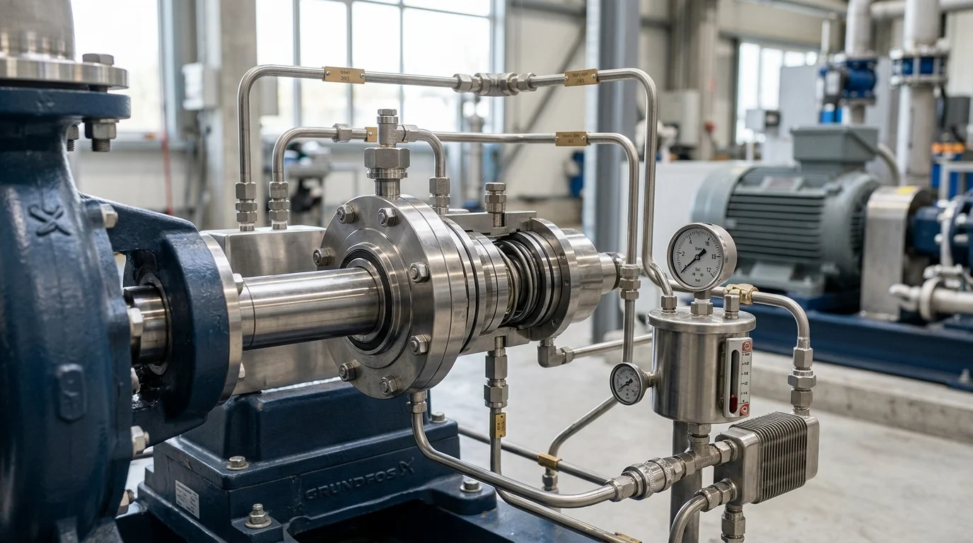
Mechanical seal systems represent the primary containment barrier in modern centrifugal pumps, agitators, and rotating fluid-handling equipment. While their fundamental purpose is to prevent process fluids from escaping into the environment, they are inherently complex tribological systems that require precise operating conditions to function correctly. When these systems fail to maintain optimal containment, the resulting excessive leakage triggers a cascade of commercial consequences.
The financial impact of mechanical seal failure is rarely limited to the purchase price of a replacement component. Instead, it reverberates throughout the entire production facility, affecting maintenance budgets, production quotas, and regulatory compliance profiles. Understanding this commercial impact is the first step in justifying the engineering resources required to diagnose and permanently resolve chronic sealing issues.
Leakage as a Lifecycle Cost Issue
The financial burden of mechanical seal leakage extends far beyond the initial capital expenditure for the seal. In continuous process environments such as petrochemical refining and power generation, mechanical seals account for up to 70% of all centrifugal pump maintenance costs. A facility experiencing chronic leakage may see its Mean Time Between Failures (MTBF) drop from an industry-standard 36 months to fewer than 12 months, effectively increasing the lifecycle cost of that pumping system by over 300%.
Direct costs accumulate rapidly during a failure event. Beyond the replacement hardware, which can range from $500 for a standard component seal to over $15,000 for highly engineered API 682-compliant models, operators must factor in the labor required for teardown, decontamination, and reinstallation. With specialized mechanical labor rates frequently exceeding $150 per hour, a single seal replacement can easily incur $2,000 to $5,000 in direct maintenance costs. Furthermore, dual seal arrangements suffering from inboard leakage will continuously consume expensive barrier fluids, adding a hidden but significant operational expense over the seal’s shortened lifecycle.
Production Losses and Environmental Exposure
Beyond immediate hardware and labor costs, excessive leakage introduces severe operational penalties through unplanned downtime. In continuous process industries, the loss of a critical, unspared pump can halt an entire production unit. The financial penalty for this downtime is staggering, often ranging from $10,000 to well over $100,000 per hour depending on the facility’s output capacity and current commodity prices. Even when redundant systems are available, the transition period can induce process instability, leading to off-spec product that must be flared or reprocessed.
Environmental and safety liabilities represent an equally severe commercial threat. Regulatory bodies rigorously monitor fugitive emissions, particularly Volatile Organic Compounds (VOCs) and hazardous air pollutants. Under protocols such as EPA Method 21, excessive leakage of VOCs—often defined by thresholds as stringent as 500 parts per million by volume (ppmv)—can trigger mandatory repair protocols, heavy regulatory fines, and increased inspection frequencies. In extreme cases, unmitigated leakage of flammable or toxic fluids creates explosive atmospheres or exposure hazards, risking catastrophic facility damage and severe personnel injury.
Defining Excessive Leakage in Mechanical Seal Systems
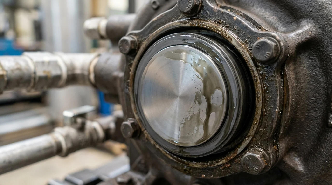
A fundamental principle of mechanical seal operation is that a microscopic fluid film must exist between the rotating and stationary faces to provide lubrication and cooling. Because this film migrates across the seal faces and eventually reaches the atmospheric side, all mechanical seals leak by design. The critical diagnostic challenge for reliability engineers is differentiating between this required, controlled fluid migration and pathological leakage indicative of system failure.
Normal Controlled Leakage vs Excessive Leakage
Differentiating between essential lubrication and excessive leakage requires established baselines based on fluid dynamics and seal geometry. For a standard contacting liquid seal operating under optimal conditions, normal leakage is virtually invisible, typically evaporating as it crosses the seal faces. When quantified, this normal baseline is generally accepted as 1 to 5 drops per minute (approximately 2.5 to 12.5 ml/hour) for standard water-like fluids on shafts up to 2 inches in diameter.
Excessive leakage occurs when the fluid film breaks down, face topography is altered, or secondary sealing elements fail, allowing fluid to bypass the engineered restriction. A seal losing more than 60 drops per minute is universally classified as failing and requires immediate intervention to prevent catastrophic face destruction or severe environmental contamination.
| Leakage Classification | Visual Indication | Volumetric Rate (Approx) | Required Action |
|---|---|---|---|
| Normal / Optimal | Invisible (evaporates) or very rare dripping | < 2.5 ml/hr (0-1 drops/min) | Continue routine monitoring. |
| Acceptable | Occasional dripping, slight moisture on gland | 2.5 – 12.5 ml/hr (1-5 drops/min) | Document and monitor for changes. |
| Marginal | Steady dripping, minor pooling | 15 – 50 ml/hr (10-20 drops/min) | Schedule inspection; check flush plans. |
| Excessive / Failure | Continuous stream, heavy spraying, vapor clouds | > 150 ml/hr (> 60 drops/min) | Isolate equipment; immediate teardown. |
Effects of Seal Arrangement, Fluid, Pressure, and Temperature
The definition of “excessive” is highly dependent on the specific seal arrangement and the physical properties of the process fluid. Single seals rely entirely on the process fluid for lubrication; if the fluid is a light hydrocarbon with high vapor pressure, the fluid film may flash into a gas before exiting the seal faces. In this scenario, excessive leakage will not manifest as liquid drops but rather as a high VOC concentration (e.g., spiking from a baseline of 10 ppm to over 1,000 ppm).
Pressure and temperature also strictly govern expected leakage rates. A seal operating at 300 psig will naturally exhibit a thicker fluid film and higher baseline leakage than an identical seal operating at 50 psig. Similarly, elevated temperatures reduce fluid viscosity, allowing more fluid to pass between the faces. Dual seal arrangements (such as API Plan 52 or 53) complicate this further; excessive leakage in a dual pressurized system often presents not as external fluid loss, but as a rapid depletion of barrier fluid pressure—such as losing more than 0.5 bar per day in a Plan 53A reservoir.
Key Leakage Indicators to Document
When leakage breaches acceptable thresholds, maintenance personnel must document specific indicators before removing the pump from service. Capturing the precise operating conditions at the exact moment the leakage was identified is critical for root cause analysis. Operators should record the volumetric rate of the leak (ml/hr), the phase of the escaping fluid (liquid, vapor, or mixed), and the exact location of the breach (e.g., between the gland plate and stuffing box, along the shaft sleeve, or directly from the seal faces).
Furthermore, documenting the system’s process parameters is essential. Engineers must record the suction and discharge pressures, fluid temperature, pump vibration levels (in inches per second or mm/s), and the status of the seal support system (e.g., flow rate and temperature of an API Plan 11 or Plan 32 flush). These documented indicators form the empirical foundation required to isolate the failure mechanism during the subsequent teardown.
Root Causes of Excessive Mechanical Seal Leakage
Identifying the root cause of excessive seal leakage requires moving beyond the immediate symptom of fluid loss to understand the mechanical, thermal, or chemical forces that compromised the sealing barrier. Mechanical seals are precision devices, often manufactured with face flatness tolerances measured in helium light bands (approximately 0.000011 inches or 0.3 microns). Because of this extreme precision, even minor deviations in operation, installation, or material compatibility can initiate a rapid failure sequence.
Dry Running, Pressure Spikes, and Temperature Excursions
The fluid film between seal faces is highly sensitive to process stability. Dry running occurs when the pump loses prime, entrains excessive air, or when a flush plan fails, starving the seal faces of lubrication. Without this fluid film, the coefficient of friction skyrockets. Face temperatures can spike rapidly, often exceeding 400°F (204°C) within seconds. This thermal shock causes face distortion (coning or bulging), heat checking (microscopic radial cracks on hard faces like tungsten carbide), and ultimate loss of the flat sealing gap.
Similarly, pressure spikes and temperature excursions push the seal beyond its design envelope. A standard component seal rated for 400 psig can suffer severe face deflection or O-ring extrusion if subjected to a sudden water hammer event or dead-heading of the pump. Temperature excursions beyond the boiling point of the process fluid cause the fluid film to vaporize prematurely, blowing the seal faces apart (popping) and causing immediate, heavy leakage that persists even after temperatures normalize.
Installation Errors, Shaft Runout, and Misalignment
Precision equipment demands precision assembly and alignment. Installation errors are among the leading causes of premature seal failure. If a seal gland is tightened unevenly, the stationary face will not sit perpendicular to the rotating assembly, causing the faces to open and close slightly with every revolution. This dynamic tracking issue leads to edge chipping, accelerated wear, and heavy leakage.
Equipment condition plays an equally critical role. Maximum allowable radial shaft runout is typically 0.001 to 0.002 inches (0.025 to 0.05 mm) Total Indicator Reading (TIR). Axial end play should generally not exceed 0.005 inches (0.13 mm). If the pump bearings are worn or the shaft is bent, the resulting vibration and deflection force the seal faces to absorb the kinetic energy. The springs or bellows within the seal cannot compensate for severe misalignment at 3,600 RPM, leading to fluid film collapse and excessive leakage.
Material Incompatibility and Elastomer Degradation
Secondary sealing elements, particularly elastomeric O-rings, are highly vulnerable to chemical attack and thermal degradation. Specifying the wrong elastomer for the process fluid guarantees eventual leakage. For example, utilizing a standard FKM (Viton) O-ring in an application pumping hot amines or steam above 300°F (149°C) will result in rapid cross-linking and hardening. The O-ring loses its elasticity, takes a permanent compression set, and fails to seal the gap between the shaft and the rotating face.
Chemical incompatibility often manifests as swelling, blistering, or dissolving of the elastomer. An O-ring that exhibits greater than 15% volume swell due to chemical absorption will extrude from its groove, binding the seal’s dynamic components. If the flexible elements cannot move axially to compensate for face wear, the seal faces will separate, resulting in a sudden and massive leak.
Diagnosing Leakage Symptoms and Failure Modes
Translating visible leakage into a definitive root cause requires a systematic diagnostic approach. Because mechanical seals are enclosed within the pump stuffing box or seal chamber, the internal damage is hidden during operation. Reliability engineers must rely on external leakage signatures and rigorous post-mortem teardown procedures to identify the specific failure mode.
Leakage Pattern Comparison Table
Different failure modes produce distinct leakage signatures. Observing when and how the seal leaks provides critical clues before the equipment is even shut down. A seal that leaks only while stationary points to different root causes than one that leaks heavily while rotating. The following table outlines common leakage patterns and their highly probable failure modes.
| Observed Leakage Pattern | Most Probable Root Cause | Recommended Diagnostic Action |
|---|---|---|
| Steady dripping while pump is stationary | Damaged secondary seals (O-rings), severe face scoring, or thermal distortion. | Perform static pressure test; inspect O-rings for compression set. |
| Heavy spray only during rotation | Shaft runout, severe misalignment, or dynamic tracking failure. | Measure shaft TIR and axial end play using dial indicators. |
| Intermittent “popping” or spitting | Fluid flashing/vaporization between faces due to inadequate vapor margin. | Check stuffing box pressure and fluid temperature against vapor pressure curve. |
| Black dust accumulation with fluid | Dry running causing carbon face disintegration. | Verify flush plan flow rates; check for pump cavitation. |
| Leakage from gland plate gasket | Uneven gland bolt torque or gasket chemical degradation. | Check bolt torque sequence; verify gasket material compatibility. |
Single, Dual, Cartridge, and Split Seal Considerations
The diagnostic approach must be tailored to the specific seal configuration. Single seals provide direct visual evidence of process fluid leakage, making external diagnosis relatively straightforward. However, dual seals (utilizing API Plans 52, 53A/B/C, or 54) mask process leakage. In a dual pressurized system, inboard seal failure is diagnosed by monitoring the barrier fluid. A rapid drop in barrier fluid pressure or a sudden increase in barrier fluid reservoir level (in unpressurized tandem setups) indicates inboard face failure.
Cartridge seals, which are pre-assembled on a sleeve, minimize installation errors but require careful inspection of the gland gasket and sleeve O-rings during diagnostics. Split seals, which are assembled in halves directly on the equipment, are highly sensitive to face alignment during assembly. If a split seal leaks heavily immediately upon startup, the primary diagnostic focus should be on the alignment of the split faces and the integrity of the joining elastomer joints, rather than wear.
Step-by-Step Diagnostic Process
A rigorous diagnostic teardown prevents the destruction of critical evidence. The process begins before removal: isolate the equipment, lock out the motor, and perform a low-pressure static air test (e.g., 25 psig) to identify the exact leak path. Once removed, the seal must not be cleaned immediately, as chemical deposits, carbon dust, and debris provide vital clues regarding the operating environment.
Inspect the primary seal faces under magnification. A healthy seal face will display a uniform, polished 360-degree wear track. A wear track that is wider than the opposing face indicates severe shaft deflection or bearing wear. A track that fades in and out indicates face distortion (often caused by over-tightening the gland). Finally, all secondary elastomers should be measured for volume swell and tested for hardness (Shore A durometer) to verify material compatibility and thermal degradation.
Reducing Repeat Leakage and Improving Seal Reliability
Eliminating chronic mechanical seal leakage requires a transition from reactive component replacement to proactive reliability engineering. Once the root cause of a failure is definitively identified, operators must implement corrective actions that address the fundamental system flaws. These improvements generally fall into three categories: optimizing the initial design and specification, executing strategic retrofits, and integrating seal reliability into broader asset management practices.
Design and Specification Decisions That Reduce Leakage Risk
The most effective method for preventing leakage is engineering the risk out of the system during the specification phase. Selecting the appropriate seal face materials is critical. For highly abrasive applications, upgrading from a standard carbon/silicon carbide pairing to hard-on-hard faces (silicon carbide vs. tungsten carbide) prevents rapid face scoring. In applications prone to low lubricity, utilizing specialized face topographies, such as laser-machined hydrodynamic grooves, can enhance fluid film retention and prevent dry running.
Equally important is the specification of the environmental control system. A mechanical seal is only as reliable as its flush plan. Implementing an API Plan 32 to inject a clean, cool external flush into the stuffing box can dramatically extend seal life in slurry applications. Engineers must ensure this flush system is properly sized, maintaining a minimum flow velocity of 15 ft/s in the throat bushing clearance to effectively exclude particulates and dissipate frictional heat.
Repair, Retrofit, and Upgrade Decisions
When existing equipment suffers from repeat failures, direct replacement in kind is often a flawed strategy. Retrofitting from older component seals to modern cartridge seals is a highly effective upgrade; cartridge designs pre-set the spring compression and face alignment at the factory, which can reduce installation-related failures by up to 40%.
Material upgrades during repair cycles also yield significant reliability gains. Upgrading standard elastomeric O-rings to perfluoroelastomers (FFKM, such as Kalrez) provides near-universal chemical resistance and pushes the thermal limit above 500°F (260°C). While FFKM O-rings may introduce a cost premium of $200 to $500 per seal, this initial expense is rapidly offset by the prevention of a single catastrophic leakage event and the subsequent extension of the seal’s MTBF.
Conclusion: Connecting Root Cause Control to Lower Total Cost
The control of mechanical seal leakage is fundamentally tied to the broader goals of facility asset management. By moving away from treating seal failures as inevitable operational realities, facilities can drastically reduce their total cost of ownership. Achieving an optimal MTBF of greater than 60 months for heavy-duty process seals is entirely feasible when root cause analysis dictates maintenance actions.
Ultimately, improving seal reliability protects the facility’s bottom line by minimizing direct repair costs, maximizing unit uptime, and eliminating the severe regulatory risks associated with fugitive emissions. By rigorously documenting leakage indicators, performing structured teardown analyses, and upgrading specifications based on empirical data, reliability teams can transform mechanical seal systems from chronic liabilities into highly dependable containment barriers.
Key Takeaways
- Treat excessive seal leakage as a lifecycle cost issue because repeated failures can reduce pump MTBF from about 36 months to fewer than 12 months.
- Investigate operating conditions first, since dry running, insufficient flush flow, heat buildup, and pressure instability often cause leakage even when the seal design is correct.
- Check installation quality carefully because incorrect setting length, contaminated faces, damaged elastomers, or uneven gland tightening can create leakage at startup.
- Control vibration, misalignment, and shaft runout to protect the seal faces from unstable contact, accelerated wear, and premature failure.
- Select seal face and elastomer materials based on the pumped fluid, temperature, pressure, and chemical compatibility rather than relying only on dimensional fit.
- Use chronic leakage data to justify corrective engineering, because downtime can cost from $10,000 to more than $100,000 per hour in critical continuous-process services.
Frequently Asked Questions
What is considered excessive leakage in a mechanical seal system?
Excessive leakage is any seal leakage beyond the equipment maker’s limits, site standards, or regulatory thresholds. For VOC services, even readings around 500 ppmv can trigger repair requirements under common monitoring protocols.
What are the most common root causes of mechanical seal leakage?
Common causes include dry running, poor lubrication, shaft misalignment, excessive vibration, wrong seal material selection, improper installation, thermal distortion, and inadequate flush or barrier fluid conditions.
Can a mechanical seal operate with zero leakage?
Most mechanical seals require a microscopic fluid film between the faces, so true zero leakage is uncommon. The goal is controlled leakage that supports lubrication while staying within safety, environmental, and process limits.
How does poor installation lead to seal leakage?
Incorrect setting length, uneven gland tightening, damaged O-rings, contaminated faces, or improper sleeve preparation can distort the seal faces and prevent proper contact, causing immediate or premature leakage.
Why does pump vibration damage mechanical seals?
Vibration causes unstable face contact, shaft runout, and repeated loading of secondary seals. Over time, this leads to face wear, heat generation, chipped components, and loss of sealing performance.

Post time: Aug-01-2026