


Introduction
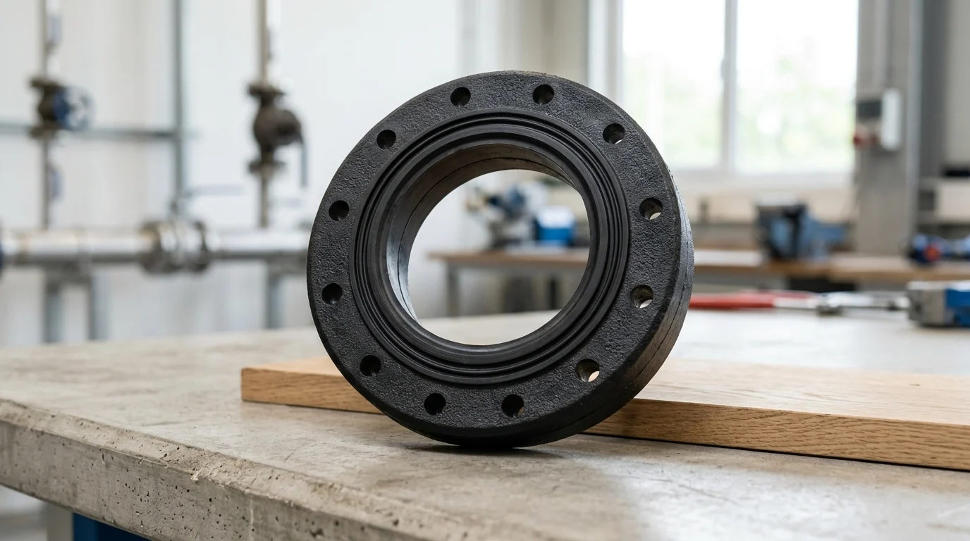
Seal integrity in gas pipelines is a core factor in both process safety and environmental performance. Small failures at flanges, valves, compressor stations, or metering equipment can escalate into methane emissions, service interruptions, costly repairs, and, in severe cases, major containment incidents. As operating pressures rise and gas compositions become more demanding, sealing systems must withstand greater mechanical stress, temperature variation, and chemical exposure without losing reliability. This article explains why gas pipeline seals matter, where integrity risks typically develop, and how seal performance influences emissions control, uptime, and regulatory compliance, providing a clear foundation for the technical discussion that follows.
Why Gas Pipeline Seal Integrity Matters
In high-pressure transmission networks, gas pipeline seal integrity serves as the primary defense against catastrophic containment loss and environmental contamination. The operational reliability of midstream infrastructure depends heavily on the mechanical and chemical stability of sealing elements located at flanges, valves, compressor stations, and metering skids. As pipeline operators push for higher throughput and transition to handling complex gas mixtures, the demands placed on these sealing interfaces have escalated exponentially.
Leak prevention, emissions control, and incident costs
Maintaining hermetic boundaries is critical not only for operational continuity but also for minimizing the financial and environmental toll of fugitive emissions. Methane, the primary component of natural gas, has a Global Warming Potential (GWP) roughly 28 to 36 times greater than carbon dioxide over a 100-year period. Industry data suggests that minor, continuous leaks across pipeline infrastructure can account for up to 30% of total fugitive methane losses in the midstream sector.
Beyond environmental impact, seal failures carry profound financial consequences. An unplanned pipeline shutdown resulting from a blown flange gasket or a compromised compressor valve seal can halt transmission entirely. For a major high-capacity transmission line, unplanned downtime costs routinely exceed $250,000 per day in deferred revenue, excluding the immediate costs of emergency mobilization, excavation, and component replacement.
Operating conditions that compromise seal integrity
Pipeline seals must withstand aggressive dynamic environments that actively degrade material integrity. Pressure cycling, thermal shock, and exposure to aggressive media such as hydrogen sulfide (H2S) or carbon dioxide (CO2) in sour gas applications continuously stress sealing elements.
One of the most severe operating conditions is Rapid Gas Decompression (RGD), also known as Explosive Decompression (ED). This phenomenon occurs when system pressure drops precipitously—often exceeding a 1,000 psi reduction in under an hour. Gas that has permeated the molecular structure of an elastomer seal expands rapidly, causing internal blistering, fissuring, and ultimate catastrophic rupture of the cross-linked polymer chain. Mitigating these conditions requires precise material formulation and rigorous mechanical design.
What Defines Gas Pipeline Seal Performance
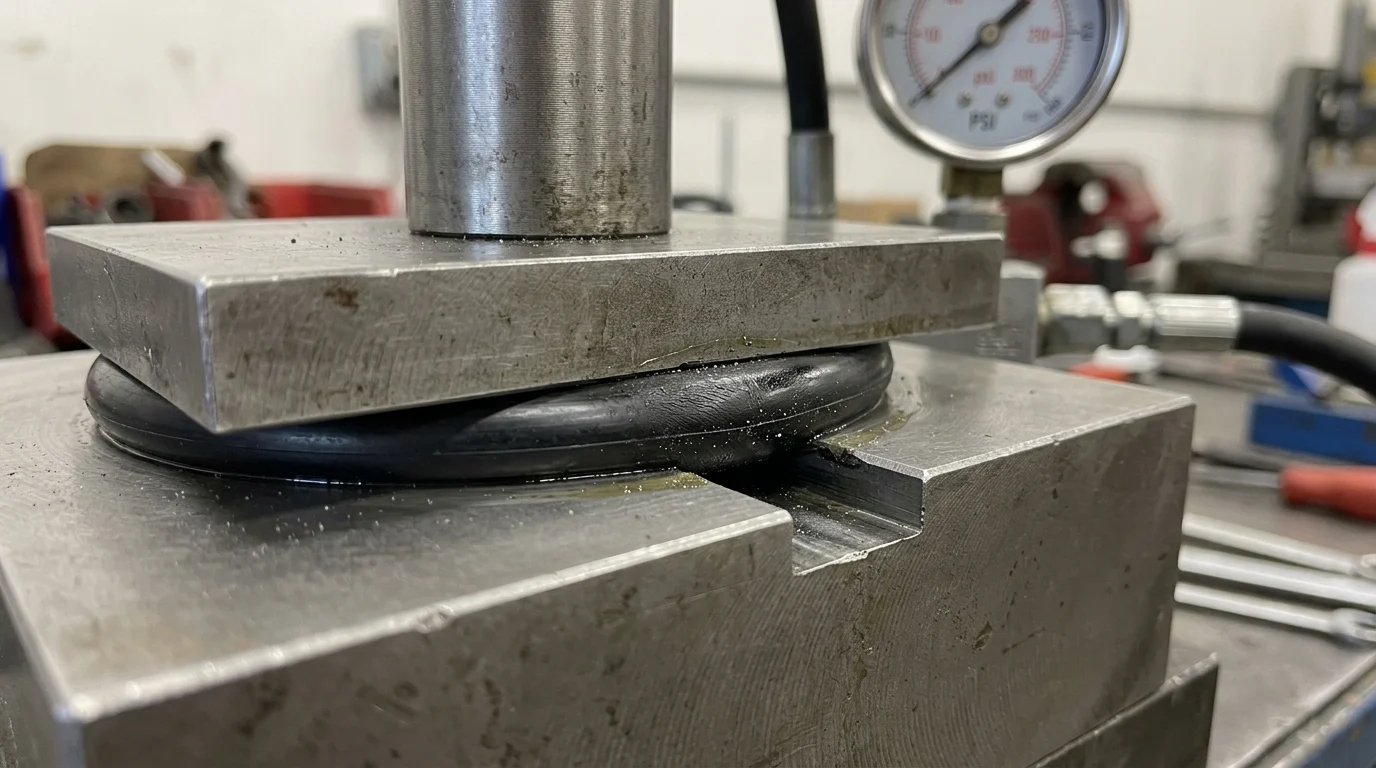
Seal performance is dictated by the intersection of material science, geometric design, and the physical constraints of the operating environment. A seal must maintain sufficient contact stress against mating hardware across all anticipated pressure and temperature fluctuations without undergoing permanent plastic deformation or chemical degradation.
Seal materials, geometries, and pressure-temperature limits
The fundamental architecture of a gas pipeline seal includes O-rings, spiral wound gaskets, ring type joint (RTJ) gaskets, and specialized lip seals. Each geometry is engineered to manage specific stress distributions. For example, API 6A standard flanges utilized in high-pressure wellhead and transmission applications routinely require RTJ metal seals rated to withstand up to 15,000 psi. These gaskets rely on high localized contact stress to coin the metal into the flange groove, creating a leak-tight barrier.
In lower pressure applications, elastomeric O-rings and spiral wound gaskets with graphite or PTFE filler provide excellent recovery and conformability. However, their pressure-temperature limits are bounded by the extrusion resistance of the polymer and the yield strength of the reinforcing materials.
Comparing elastomer, thermoplastic, and metal seals
The selection between elastomer, thermoplastic, and metal seals involves weighing elasticity against thermal and chemical durability.
| Material Category | Typical Compounds | Temp Range | Max Pressure Rating | H2S Resistance | Typical Application |
|---|---|---|---|---|---|
| Elastomer | HNBR, FKM, FFKM | -40°C to 300°C | Up to 5,000 psi | Moderate to High | Compressor valves, static O-rings |
| Thermoplastic | PTFE, PEEK, PCTFE | -200°C to 260°C | Up to 10,000 psi | High | Ball valve seats, backup rings |
| Metal | Inconel 718, 316L SS | Cryogenic to 1000°C | > 15,000 psi | Excellent | API 6A flanges, critical joints |
Elastomers provide superior resilience and are forgiving of minor surface imperfections, but they are susceptible to extrusion and RGD. Thermoplastics like PEEK offer exceptional extrusion resistance and chemical inertness, bridging the gap between polymers and metals. Metal seals are reserved for the most extreme environments, offering absolute chemical compatibility and temperature resistance, though they require pristine mating surfaces to function correctly.
Key criteria for seal selection
Selecting the optimal seal requires evaluating the specific gas composition, maximum operating pressure (MOP), and extreme temperature ranges. A critical criterion in the oil and gas sector is compliance with the NORSOK M-710 or ISO 23936-2 standards, which dictate the testing and approval of non-metallic materials for sour service and RGD environments.
When H2S concentrations exceed 2% or partial pressures breach specific thresholds, operators must specify materials compliant with NACE MR0175/ISO 15156 to prevent sulfide stress cracking in metal components and rapid embrittlement in polymers. Engineers must cross-reference these chemical requirements with the mechanical extrusion gaps present in the hardware to ensure the chosen material will not shear under peak pressure.
How to Verify Seal Integrity Through Design and Installation
Even the most advanced sealing materials will fail if the system is improperly designed or assembled. Verifying seal integrity requires stringent controls over hardware manufacturing tolerances, surface finishes, and the mechanical procedures used during installation.
Installation controls, surface preparation, and torque practices
The mating surfaces of flanges and valve housings must be machined to precise roughness parameters to ensure the seal can conform properly without allowing permeation paths. For standard elastomeric and spiral wound gaskets, surface finishes typically require a roughness average (Ra) of 3.2 to 6.3 µm. Conversely, metal-to-metal seals demand highly polished surfaces, often requiring an Ra of less than 0.8 µm.
Bolt torque practices are equally critical. Uneven bolt loading causes flange rotation and uneven compression of the gasket, leading to localized extrusion or bypass leaks. Manual torquing without calibrated equipment can result in bolt preload scatter of up to ±30%. To achieve the uniform compression required for high-integrity gas seals, operators increasingly rely on hydraulic tensioning systems that guarantee simultaneous and equalized bolt loading across the flange.
Inspection and testing methods
Post-installation verification relies on rigorous non-destructive testing (NDT) and pressure testing. Hydrostatic testing is the baseline requirement for structural integrity, but it is insufficient for verifying gas-tight sealing due to the differing viscosities of water and gas. Nitrogen-helium leak testing is the industry standard for critical gas infrastructure.
Under protocols such as ISO 15848-1 for fugitive emissions, valves and flanged joints are subjected to helium mass spectrometry. This testing targets stringent leak rate classifications, frequently requiring containment capabilities as tight as 10⁻⁶ mg/(s·m) for highly toxic or highly volatile gas streams. Routine field inspections utilize Optical Gas Imaging (OGI) cameras and laser-based methane detectors to identify micro-leaks during active service.
A step-by-step integrity management workflow
A robust integrity management workflow begins long before the seal is seated. The first step involves a comprehensive pre-installation audit, verifying that the seal material test reports (MTRs) match the engineering specification and that hardware dimensions are within tolerance.
The second step is the controlled installation, utilizing a documented cross-pattern torque sequence and calibrated tensioning tools. Following assembly, the system undergoes a staged pneumatic or hydrostatic pressure test, holding at 1.1 to 1.5 times the maximum allowable operating pressure (MAOP) to verify yield strength. Finally, a baseline emissions scan is conducted at normal operating pressure to establish a zero-leak state, which is recorded in the facility’s computerized maintenance management system (CMMS) for future comparative analysis.
Safety, Environmental, and Compliance Factors
The regulatory environment governing gas pipeline operations has tightened significantly, driven by global climate initiatives and stringent occupational safety standards. Seal integrity is no longer viewed merely as a maintenance metric; it is a critical compliance parameter heavily monitored by environmental agencies.
Fugitive emissions rules and process safety expectations
Regulatory bodies worldwide have established aggressive frameworks to curb Volatile Organic Compounds (VOCs) and methane emissions. In the United States, the EPA’s New Source Performance Standards (NSPS) Subpart OOOOa (Quad Oa) mandates comprehensive leak detection and repair (LDAR) programs for midstream operators. Depending on the facility classification, operators must conduct Optical Gas Imaging (OGI) surveys either quarterly or semi-annually.
Process safety expectations are strictly quantified. Under EPA Method 21, a volatile emission registering greater than 500 parts per million (ppm) is legally classified as a leak. Once identified, operators are subject to rigid compliance clocks, typically requiring an initial repair attempt within 5 days and successful mitigation within 30 days. Failure to maintain seal integrity under these parameters exposes operators to severe civil penalties and forced asset shutdowns.
Common failure modes and environmental risks
Understanding how seals fail is essential for mitigating environmental risks. Failure modes in gas pipelines are highly specific to the operational stressors applied to the joint.
| Failure Mode | Primary Cause | Visual / Physical Indicator | Prevention Strategy |
|---|---|---|---|
| Extrusion | High pressure / excessive clearance | “Nibbled” or sheared edges on the seal | Use thermoplastic backup rings; reduce hardware clearance |
| Explosive Decompression | Rapid pressure drop | Internal blisters, external fissures | Specify NORSOK M-710 RGD-resistant elastomer compounds |
| Thermal Degradation | Operating above temp limits | Hardening, embrittlement, cracking | Upgrade to high-temp fluoroelastomers (FFKM) or metal seals |
| Chemical Attack | Incompatible media (e.g., H2S, amines) | Swelling, softening, loss of tensile strength | Cross-reference media with chemical compatibility charts |
When these failures occur, the environmental risks scale rapidly. A localized extrusion failure on a main block valve can release thousands of standard cubic feet of methane before the line can be isolated and blown down. By systematically analyzing these failure modes through root cause analysis (RCA), operators can transition from reactive leak patching to proactive material specification.
How to Make Better Seal Decisions
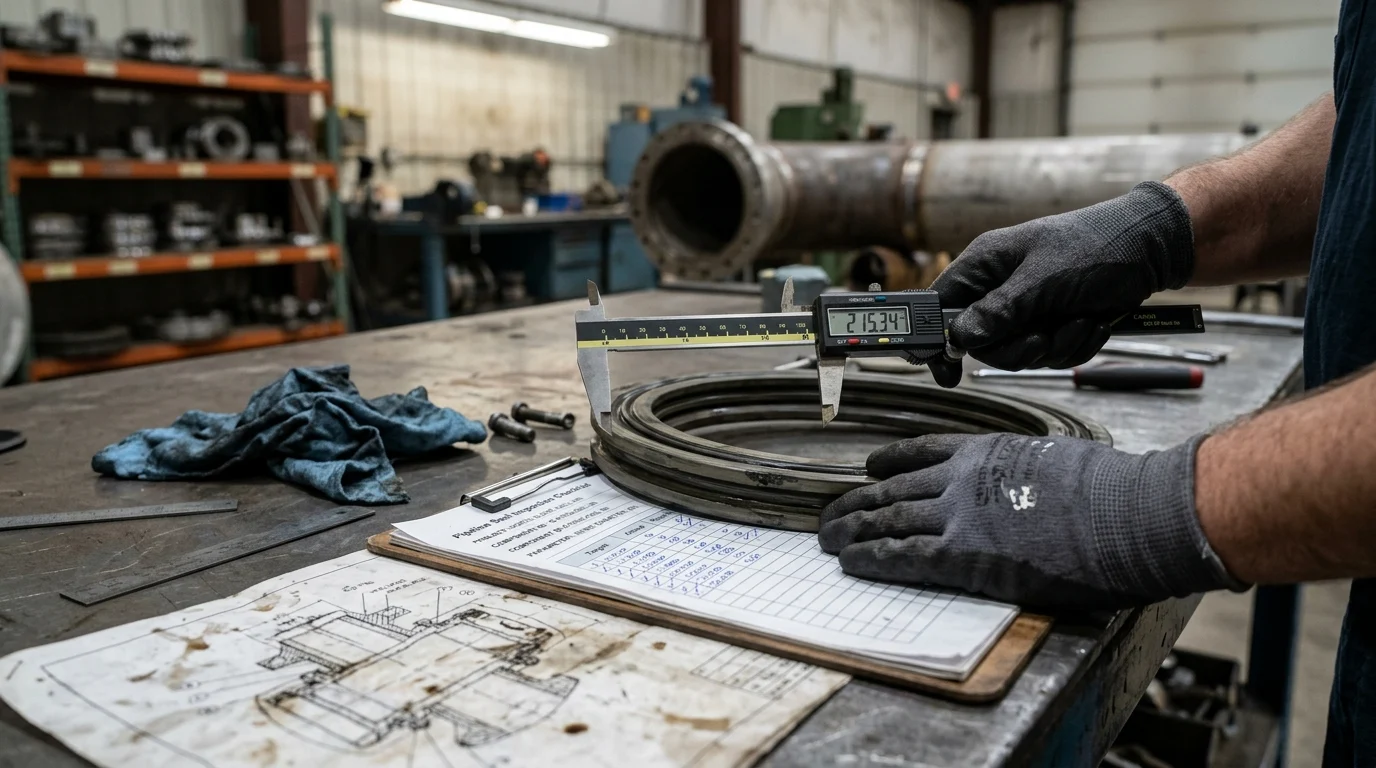
Optimizing gas pipeline seal integrity requires a strategic alignment of engineering requirements, supply chain rigor, and lifecycle cost analysis. Decision-makers must look beyond unit pricing to evaluate the broader impact of seal reliability on overall network uptime.
Procurement and supplier evaluation criteria
Supplier evaluation is a critical defense against premature seal failure. Procurement teams must demand full batch traceability, requiring EN 10204 3.1 material certification to ensure the chemical composition of the delivered product matches the qualified prototype. Auditing a supplier’s ISO 9001 quality management system ensures that compounding, molding, and curing processes are tightly controlled.
Logistical factors also dictate procurement strategies. Specialized RGD-resistant elastomers or custom-machined metal seals often carry Minimum Order Quantities (MOQ) ranging from 500 to 1,000 units for custom molds, whereas standard NBR or FKM O-rings are readily available off-the-shelf. Factoring lead times into inventory planning prevents the dangerous practice of substituting substandard, readily available seals during an emergency outage.
Balancing upfront cost against downtime risk
The most critical decision in seal procurement is balancing the initial capital expenditure against the Total Cost of Ownership (TCO) and downtime risk. Upgrading a flange from a standard Nitrile (NBR) gasket—costing approximately $5 per seal—to a highly engineered, RGD-resistant Fluoroelastomer (FKM) costing $50 per seal represents a 10x multiplier in upfront component cost.
However, this fractional increase in capital expenditure is negligible when weighed against the risk profile. Averting a single explosive decompression event prevents a potential $250,000 per day shutdown, environmental fines, and the labor costs associated with hazardous interventions. Consequently, standardizing high-grade, chemically inert, and RGD-resistant seals across all critical nodes—even where operating conditions marginally permit lower-tier materials—provides the most robust and economically sound strategy for modern gas pipeline integrity management.
Key Takeaways
- The most important conclusions and rationale for Gas Pipeline Seal
- Specs, compliance, and risk checks worth validating before you commit
- Practical next steps and caveats readers can apply immediately
Frequently Asked Questions
Why is gas pipeline seal integrity so critical?
It prevents methane leaks, unplanned shutdowns, and safety incidents. Even small seal failures at flanges, valves, or compressor stations can raise emissions and create costly downtime.
Which seal materials work best for gas pipeline service?
It depends on pressure, temperature, and gas chemistry. HNBR or FKM suit many elastomer duties, PTFE or PEEK help with extrusion resistance, and metal seals fit the highest-pressure, harshest applications.
What causes gas pipeline seals to fail early?
Common causes include pressure cycling, thermal shock, poor installation, rough sealing surfaces, and aggressive media like H2S or CO2. Rapid Gas Decompression can also crack elastomer seals after sudden pressure drops.
How can maintenance teams reduce seal leakage in pipeline-related equipment?
Match seal material to service conditions, inspect gland and flange surfaces, control installation torque, and replace worn parts during planned maintenance. Regular leak checks around valves, pumps, and compressor systems are essential.
Can Victor Seals support oil and gas sealing needs?
Yes. Victor Seals supplies mechanical seals, shaft seals, OEM-compatible replacements, and spare parts for industrial pumps used in oil, gas, petrochemical, and related maintenance applications.
Post time: May-27-2026