


Introduction
A double mechanical seal is typically chosen when leakage cannot be treated as a minor maintenance issue but as a safety, environmental, or reliability risk. In pumps handling hazardous, volatile, abrasive, or poorly lubricating fluids, a dual-seal arrangement adds a second containment barrier and usually works with a support system to stabilize operating conditions. This article explains when that added complexity is justified, what process factors drive the decision, and why seal selection affects emissions control, equipment life, and unplanned downtime. From risk reduction to operating economics, the discussion provides a practical framework for deciding when a double mechanical seal is the right engineering choice.
Why Double Mechanical Seal Selection Matters
In modern fluid handling and rotating equipment operations, the mechanical seal acts as the primary barrier between process fluids and the external environment. While single mechanical seals suffice for benign applications, the specification of a double mechanical seal system becomes a critical engineering mandate when the margin for error approaches zero. Selecting the appropriate sealing technology is not merely a matter of fluid containment; it is a fundamental determinant of plant safety, environmental compliance, and long-term operational profitability.
The decision to implement a dual seal configuration fundamentally alters the architecture of a pumping system. It introduces secondary containment, auxiliary support systems, and complex fluid dynamics that must be carefully managed. Understanding the exact risk profiles and operational consequences that necessitate this upgrade is the first step in responsible rotating equipment engineering.
Reliability and safety risks
The most immediate justification for double mechanical seals lies in the mitigation of catastrophic failure risks. In high-pressure or high-temperature applications involving flammable, toxic, or explosive fluids, the sudden failure of a primary seal can lead to immediate localized hazards. Fluids with flash points below 60°C (140°F), NFPA health hazard ratings of 3 or 4, or those containing hazardous air pollutants (HAPs) require redundant containment to prevent vapor cloud formation or fire.
By employing a secondary seal face, facilities drastically improve the Mean Time Between Failures (MTBF) of the equipment, often extending operational life by 150% to 300% compared to single seals in identical services. If the inboard seal is compromised, the outboard seal temporarily contains the process fluid or the barrier fluid, allowing operators to execute a controlled shutdown rather than facing an emergency catastrophic release.
Emissions and leakage concerns
Stringent environmental regulations compel modern facilities to achieve near-zero fugitive emissions. Regulatory frameworks, such as the EPA’s Method 21 in the United States or the Industrial Emissions Directive in Europe, enforce strict volatile organic compound (VOC) leak thresholds, frequently mandating limits below 500 parts per million (ppm), and in some jurisdictions, as low as 50 ppm.
A single seal, by design, relies on a microscopic fluid film to lubricate its faces, which inherently results in minute vaporization (typically 1 to 5 grams per hour) and emissions into the atmosphere. Double mechanical seals, particularly those utilizing a pressurized barrier fluid (API 682 Arrangement 3), completely eliminate the emission of process fluids to the atmosphere, replacing potential process leakage with trace amounts of benign barrier fluid.
Production and maintenance impact
Beyond safety and environmental mandates, seal selection heavily influences plant availability and maintenance budgets. Mechanical seal failures account for nearly 70% of all centrifugal pump maintenance interventions. A typical pump seal replacement requires between 8 to 24 hours of labor and associated downtime, which can incur production losses ranging from $10,000 to over $50,000 per hour in continuous petrochemical processes.
Double mechanical seals isolate the precision lapped seal faces from harsh process conditions. By providing a clean, cool, and highly lubricious barrier fluid, the seal faces are protected from dry running, abrasive wear, and thermal distortion, significantly extending the lifecycle of the pump and reducing unplanned maintenance interventions.
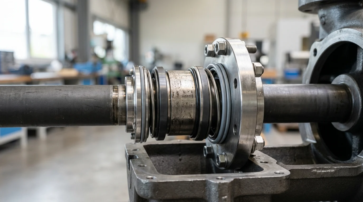
What a Double Mechanical Seal Is
A double mechanical seal, often referred to in modern engineering standards as a dual seal, consists of two independent mechanical seals operating in series or parallel within a single seal chamber. This configuration creates a cavity between the two seals that is filled with a secondary fluid, known as a buffer or barrier fluid, which serves to lubricate the seal faces, dissipate heat, and provide a secondary containment layer.
The fundamental architecture relies on the interplay between the inboard seal (which interfaces directly with the process fluid) and the outboard seal (which interfaces with the atmosphere). The dynamics of the secondary fluid dictate the exact classification and functional capability of the dual seal assembly.
Core definition and operating principle
The operating principle of a double seal depends entirely on the pressure differential maintained in the cavity between the inboard and outboard seals. When the cavity fluid is maintained at a pressure lower than the process stuffing box pressure, it is termed a “buffer fluid” (Arrangement 2). In this state, the inboard seal is lubricated by the process fluid, and any process leakage is captured by the buffer fluid.
Conversely, when the cavity fluid is pressurized to a level higher than the process pressure—typically maintained at 1.5 to 2.0 bar (22 to 29 psi) above the maximum dynamic stuffing box pressure, often requiring circulation rates of 2 to 8 liters per minute—it is termed a “barrier fluid” (Arrangement 3). Under these conditions, the barrier fluid lubricates both the inboard and outboard seal faces. If the inboard seal experiences wear, the barrier fluid leaks inward into the process, guaranteeing zero outward leakage of the hazardous process medium.
Comparison with single seals
Understanding the precise differences between single and dual seal configurations is essential for lifecycle cost and risk analysis. The addition of a secondary seal drastically changes the operational envelope of the pump.
| Feature / Metric | Single Mechanical Seal | Double Mechanical Seal (Pressurized) |
|---|---|---|
| Emissions Level | Low to moderate (film vaporization) | Zero process emissions |
| Typical Leakage Rate | 1 to 5 grams/hour to atmosphere | 0 grams/hour to atmosphere |
| Face Lubrication | Relies entirely on process fluid | Relies on clean barrier fluid |
| Dry Run Tolerance | Very poor (rapid failure) | High (sustained by barrier fluid) |
| Support System | Minimal (flush plans like API 11/32) | Extensive (API Plans 52, 53, 54) |
| Typical MTBF | 12 to 24 months | 36 to 60+ months |
Seal arrangements and face orientation
Dual seals are engineered in several distinct geometric arrangements to accommodate varying spatial constraints and pressure requirements. The legacy terminology of “back-to-back,” “face-to-face,” and “tandem” has largely been superseded by API 682 classifications, though the physical orientations remain relevant.
A back-to-back orientation places the rotating seal rings facing away from each other, which is excellent for high-pressure barrier fluids (often rated for 40 to 60 bar / 580 to 870 psi) but exposes the inboard seal hardware to the process fluid. A face-to-face orientation shares a common stationary mating ring and is often utilized in space-constrained stuffing boxes. The tandem orientation (often Arrangement 2) positions both seals facing the same direction, allowing the outboard seal to handle the full process pressure if the inboard seal fails, making it the preferred choice for high-pressure vaporizing services.
When to Use a Double Mechanical Seal
Specifying a double mechanical seal requires balancing the high initial capital expenditure against the operational necessity. Not all aggressive fluids require dual seals; advancements in single seal face materials and flush plans have expanded their capabilities. However, specific operational thresholds and fluid characteristics create non-negotiable mandates for double seal implementation.
Engineers must systematically evaluate the process fluid’s physical properties, the operating environment, and the consequences of failure to determine when the transition from a single to a dual seal is technically and economically justified.
Service conditions that justify use
Several harsh service conditions inherently justify the complexity of a dual seal. Fluids with high concentrations of abrasive particulates—typically exceeding 10% solids by weight—will rapidly degrade single seal faces. A pressurized double seal isolates these faces from the abrasives entirely.
Additionally, fluids with poor lubricity, such as light hydrocarbons with viscosities below 0.5 cP, non-lubricating solvents, or hot water, often flash to vapor across a single seal face, causing dry running and thermal cracking. Process fluids operating near their vapor pressure require a dual seal setup where a stable, lubricating barrier fluid can maintain the vital fluid film between the rotating and stationary faces.
Key selection criteria
The primary selection criteria revolve around temperature, pressure, toxicity, and polymerization risks. Applications operating at extreme temperatures (e.g., above 200°C / 400°F) often require double seals with an external cooling loop to maintain the seal faces within their thermal limits and prevent elastomer degradation.
Polymerizing fluids, which harden or crystallize upon contact with atmospheric oxygen, present a unique challenge. If a single seal is used, the minute atmospheric leakage will crystallize on the atmospheric side of the seal, leading to rapid abrasive wear and hang-up of the dynamic O-rings. A dual seal with a compatible barrier fluid prevents atmospheric exposure and subsequent crystallization.
| Fluid Characteristic | Typical Threshold / Trigger | Recommended API 682 Arrangement |
|---|---|---|
| High Toxicity / H₂S | > 10 ppm occupational exposure limit | Arrangement 3 (Pressurized) |
| High Particulate Load | > 10% suspended solids by weight | Arrangement 3 (Pressurized) |
| High Vapor Pressure | Vapor margin < 0.35 bar (5 psi) | Arrangement 2 or Arrangement 3 |
| Polymerizing Nature | Reacts/crystallizes with atmospheric O₂ | Arrangement 3 (Pressurized) |
Practical selection workflow
The practical workflow for seal selection should adhere to established industry frameworks, such as the API 682 Annex A selection procedure. The workflow begins with identifying the fluid hazard classification. If the fluid is highly toxic or highly flammable, Arrangement 3 (pressurized double seal) is automatically selected.
If the fluid is non-hazardous, the engineer assesses the fluid’s physical properties (e.g., vapor margins below 0.35 bar, viscosities under 0.5 cP, or particulate loads exceeding 10%). If these properties fall outside the operational limits of a single seal, the workflow diverts to an Arrangement 2 (unpressurized dual seal) or Arrangement 3, depending on whether the primary goal is backup containment or absolute face isolation.
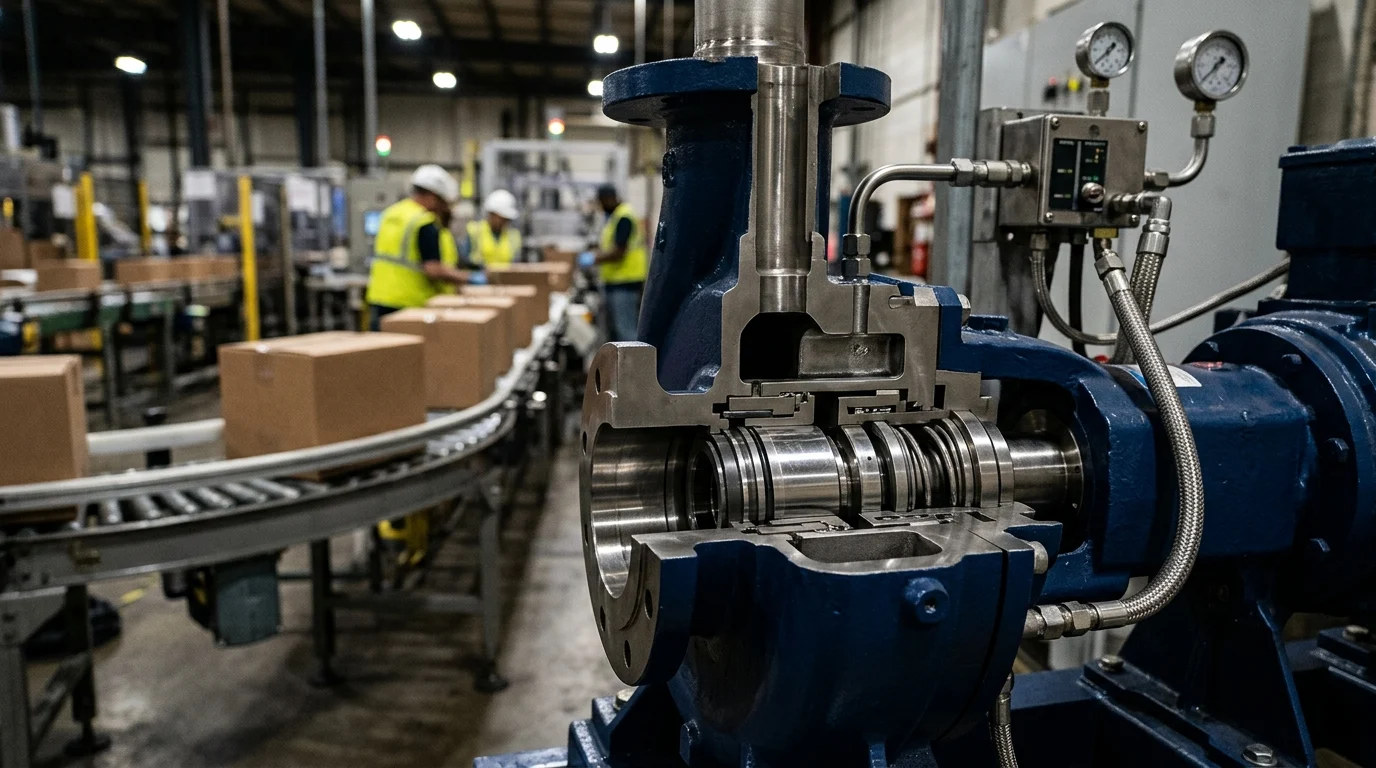
Engineering and Compliance Trade-Offs
The implementation of a double mechanical seal is never a standalone equipment upgrade; it mandates the integration of complex auxiliary support systems. These systems govern the pressure, temperature, and cleanliness of the buffer or barrier fluid, and their design is just as critical as the seal itself.
Engineers face a myriad of trade-offs when designing these systems, balancing strict compliance with international standards against the physical space limitations of the plant, utility availability, and material compatibility.
Support systems and API Plans
Dual seals rely entirely on API piping plans to function. An unpressurized dual seal typically utilizes API Plan 52, which circulates a buffer fluid from an external reservoir (commonly 12 to 20 liters in capacity, designed to dissipate 1 to 5 kW of seal face heat). This plan requires a connection to a flare or vapor recovery system to safely manage inboard seal leakage.
Pressurized dual seals utilize API Plan 53 (A, B, or C) or Plan 54. Plan 53A uses a gas-pressurized reservoir, limited to about 10.3 bar (150 psi) to prevent gas absorption into the barrier fluid. For higher pressures, Plan 53B utilizes a bladder accumulator, while Plan 53C uses a piston accumulator driven by process pressure. Plan 54, the most complex, utilizes a centralized external lubrication skid to supply barrier fluid to multiple pumps simultaneously.
Materials, cooling, and piping design
Material selection within the seal and support system must account for both the process medium and the barrier fluid. Seal faces are typically constructed from premium materials like sintered Silicon Carbide (SiC) or Nickel-bound Tungsten Carbide (TC) to handle high pressure-velocity (PV) values, often exceeding 35,000 bar-m/s (1,000,000 psi-ft/min).
Secondary sealing elements (O-rings) dictate the thermal boundaries of the system. While standard Fluoroelastomers (FKM) are suitable up to 200°C, specialized Perfluoroelastomers (FFKM) are required for temperatures approaching 320°C (608°F). Furthermore, the piping design for the cooling loops must minimize friction losses; using tubing smaller than 0.5 inches (12.7 mm) in diameter can restrict thermosyphon flow, leading to catastrophic seal overheating.
Compliance and plant standards
Compliance with international standards ensures baseline safety and reliability but introduces significant engineering constraints. In the oil, gas, and petrochemical sectors, API 682 (4th Edition) and ISO 21049 dictate stringent requirements for seal chamber dimensions, 100-hour dynamic qualification test procedures, and instrumentation.
For facilities operating in explosive atmospheres, compliance with the ATEX Directive (in Europe) or
How to Make the Final Decision
Key Takeaways
- The most important conclusions and rationale for Double Mechanical Seal
- Specs, compliance, and risk checks worth validating before you commit
- Practical next steps and caveats readers can apply immediately
Frequently Asked Questions
When should a double mechanical seal be used?
Use it when pumped media is toxic, flammable, abrasive, high-temperature, or likely to crystallize, and when leakage must be minimized for safety or compliance.
Why is a double mechanical seal better than a single seal in hazardous service?
It adds a second sealing interface and a buffer or barrier fluid, so if the primary seal degrades, leakage is contained long enough for controlled maintenance or shutdown.
What is the difference between buffer fluid and barrier fluid?
Buffer fluid is usually unpressurized and supports the outer seal; barrier fluid is pressurized above seal chamber pressure to prevent process fluid from reaching the atmosphere.
Can Victor Seals supply OEM-compatible double mechanical seals for industrial pumps?
Yes. Victor Seals provides OEM-compatible and replacement sealing solutions for many pump brands used in chemical, marine, oil and gas, and water applications.
How can a double mechanical seal reduce pump maintenance downtime?
By keeping seal faces cooler, cleaner, and better lubricated, it reduces dry running, wear, and sudden leakage, which helps extend seal life and cut unplanned stoppages.
Post time: May-30-2026