


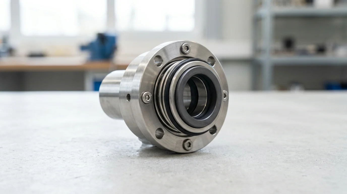
Why Mechanical Seal Leakage Matters
The reliable operation of industrial fluid processing systems depends heavily on the integrity of the centrifugal pump mechanical seal. When these seals fail, the consequences extend beyond mere fluid loss, encompassing environmental hazards, unplanned downtime, and severe safety risks. Industry reliability studies consistently indicate that mechanical seal failures account for approximately 69% of all centrifugal pump failures, making seal integrity the primary focal point for mean time between failure (MTBF) optimization. Understanding the root causes of mechanical seal leakage is paramount for maintenance engineers and reliability professionals aiming to maximize asset lifecycle and minimize operational expenditures.
Addressing these root causes requires a fundamental understanding of how a centrifugal pump mechanical seal functions under dynamic conditions. The seal is not a static barrier but a highly engineered dynamic fluid containment device that relies on precise mechanical forces, fluid dynamics, and thermodynamics.
What Counts as Mechanical Seal Leakage
To accurately diagnose issues, one must first understand what constitutes a centrifugal pump mechanical seal leakage mechanism. A mechanical seal operates by maintaining a microscopic fluid film between a rotating face and a stationary face. This fluid film, typically measuring between 0.00005 and 0.00015 inches (1.27 to 3.81 micrometers) in thickness, provides essential lubrication and cooling. As the fluid migrates across the seal faces from the high-pressure fluid side to the low-pressure atmospheric side, it undergoes a pressure drop and often a phase change, vaporizing before it exits.
Because of this continuous fluid migration, all mechanical seals technically leak; however, in a properly functioning seal, this ‘leakage’ is typically a non-visible vapor. Visible liquid leakage occurs when the fluid film thickness exceeds design parameters, allowing liquid to pass through without vaporizing, or when the seal faces are physically damaged, creating a macroscopic leak path. The transition from vapor emission to visible liquid droplet formation marks the boundary between normal operation and a developing seal issue.
Acceptable Leakage vs. Failure Symptoms
Distinguishing between acceptable operational weeping and actual failure symptoms is a critical diagnostic skill. Acceptable leakage rates vary significantly depending on the seal design, face materials, shaft diameter, rotational speed, and the specific gravity and vapor pressure of the pumped fluid. For many light hydrocarbons and high-temperature water applications, zero visible leakage is expected because the fluid flashes to vapor. Conversely, for heavier lubricating oils, an acceptable leakage rate might be quantified as 2 to 60 drops per minute.
When leakage exceeds these baseline expectations, or when the nature of the leakage changes suddenly, it indicates a breach of the seal faces or secondary sealing elements. The table below outlines the distinction between normal fluid dynamics and definitive failure symptoms.
| Leakage Type | Visual Characteristic | Typical Rate | Root Cause Indication |
|---|---|---|---|
| Normal Weeping | Invisible vapor or rare droplet | < 5 drops/hour | Stable fluid film vaporization |
| Heavy Oil Seepage | Slow, steady accumulation | 20-60 drops/minute | Expected for high-viscosity lubricating fluids |
| Spraying / Misting | Visible aerosol cloud | Unmeasurable | Face distortion or catastrophic O-ring blowout |
| Steady Stream | Continuous liquid flow | > 0.5 GPM | Shattered seal faces or gross installation error |
Installation and Alignment Causes
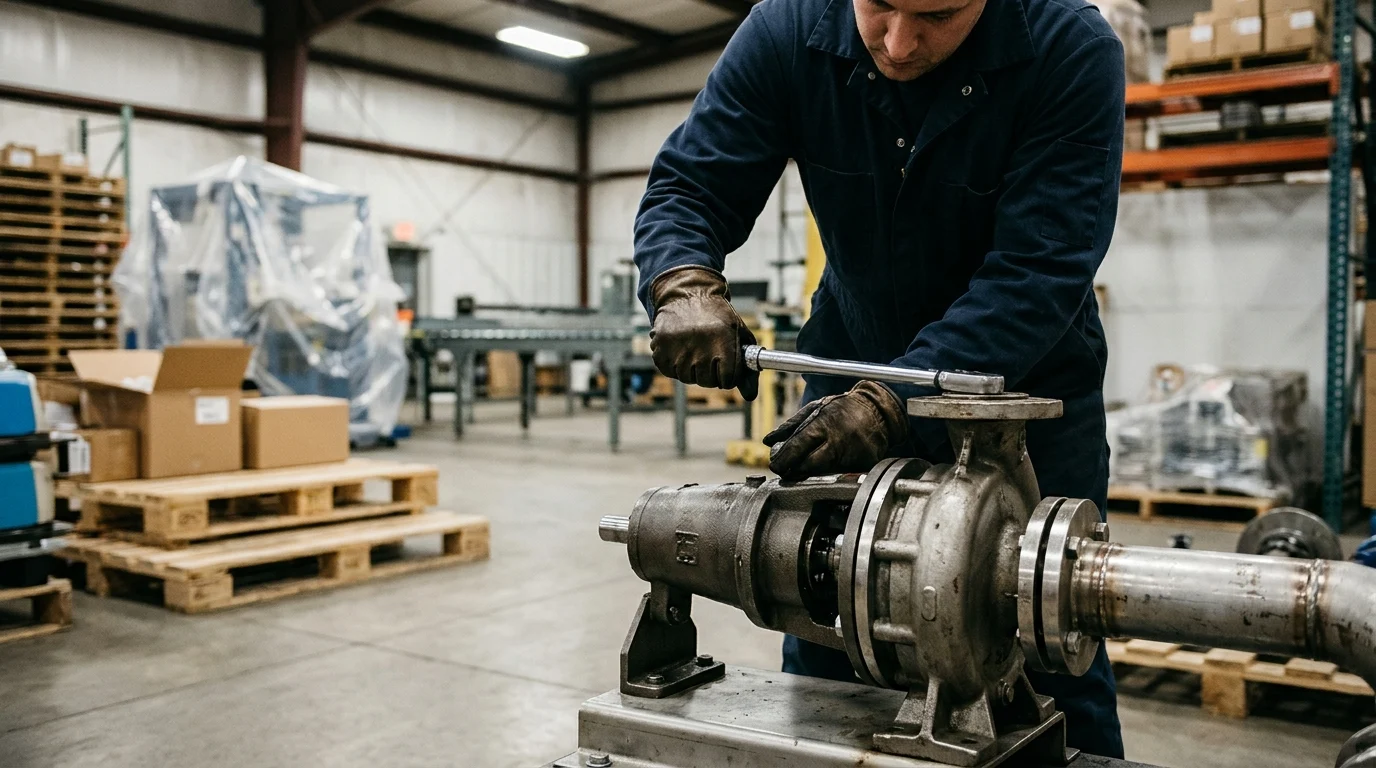
Even the most robustly engineered centrifugal pump mechanical seal will fail prematurely if subjected to improper installation or suboptimal mechanical alignment. The transition from static assembly to dynamic operation requires strict adherence to geometric tolerances. When these tolerances are exceeded, the seal faces cannot maintain the parallel alignment necessary for a stable fluid film, leading to localized contact, accelerated wear, and rapid leakage.
Pump manufacturers and seal OEMs specify exact dimensional requirements that must be verified before and during the installation process. Overlooking these geometric prerequisites is a leading root cause of infant mortality in mechanical seals, often resulting in catastrophic leakage within the first 48 hours of operation.
Incorrect Seal Installation
Incorrect seal installation encompasses a wide range of procedural errors made during pump assembly. One of the most critical parameters is the seal working length. If the seal is set incorrectly on the shaft, the springs or bellows will not provide the correct closing force. A deviation of just +/- 0.015 inches (0.38 mm) from the specified working length can result in either insufficient face pressure, allowing the fluid film to blow open the faces, or excessive pressure, destroying the fluid film and causing severe heat generation.
Furthermore, improper handling of the seal components frequently compromises integrity before the pump is even started. Touching the lapped seal faces with bare hands transfers oils and particulate matter, disrupting the microscopic flatness required for sealing. Failure to tighten drive collar set screws evenly can cause the rotating assembly to run out of square, while pinching or rolling secondary O-rings during insertion over shaft shoulders creates immediate leak paths along the sleeve.
Misalignment, Pipe Strain, and Soft Foot
Mechanical alignment extends beyond the internal pump components to the entire pump and motor drivetrain. Misalignment between the pump and motor shafts generates severe radial and axial forces that are transmitted directly to the mechanical seal. While flexible couplings can accommodate slight misalignments, they do not eliminate the forces transferred to the pump shaft. Industry standards dictate that shaft runout should not exceed 0.002 inches Total Indicator Reading (TIR) at the seal face.
In addition to shaft misalignment, pipe strain and soft foot conditions severely distort the pump casing. When heavy piping is forced into connection with the pump flanges without proper support, the casing twists, displacing the stationary seal gland relative to the rotating shaft. This angular misalignment forces the seal faces to open and close slightly with each revolution, a phenomenon known as ‘face tracking.’ At standard motor speeds like 3,600 RPM, the seal faces cannot respond fast enough to remain closed, resulting in significant leakage. Vibration monitoring can often detect these issues, with acceptable overall vibration limits typically falling below 0.15 inches/second RMS for healthy centrifugal pumps.
Operating Condition Causes
The operational environment within the pump casing directly dictates the longevity of the centrifugal pump mechanical seal. Process variations, process upsets, and deviations from the pump’s intended hydraulic design points create hostile conditions that degrade seal faces and secondary elastomers. A mechanical seal relies entirely on the pumped fluid or an external flush for cooling and lubrication; therefore, fluid condition stability is non-negotiable.
Operating a centrifugal pump outside of its prescribed parameters forces the mechanical seal to absorb the brunt of hydraulic instability. Recognizing and mitigating adverse operating conditions is essential for preventing premature seal leakage.
Dry Running and Poor Lubrication
Dry running is perhaps the most destructive operating condition for a centrifugal pump mechanical seal. When a pump loses prime, or if suction flow is interrupted, the seal faces are deprived of their lubricating fluid film. Without lubrication, the coefficient of friction between the rotating and stationary faces skyrockets, leading to immediate and extreme heat generation. Localized temperatures at the seal faces can easily exceed 400°F (204°C) within seconds of a dry run event.
This sudden thermal spike causes the seal faces to expand unevenly, leading to severe thermal distortion and ‘heat checking’—a network of microscopic radial cracks that propagate across the seal face. Once heat checking occurs, the seal faces act like milling cutters, rapidly destroying each other and causing massive leakage upon the reintroduction of fluid. Maintaining adequate Net Positive Suction Head available (NPSHa) to exceed the required (NPSHr) by a safe margin is critical to preventing flashing and dry running at the seal faces.
Off-Design Flow, Vibration, and Thermal Stress
Operating a centrifugal pump significantly away from its Best Efficiency Point (BEP) induces severe hydraulic instability. When a pump operates below 60% of its BEP or near dead-head conditions, the internal pressure distribution around the impeller becomes highly asymmetrical. This asymmetry generates immense radial thrust loads that deflect the pump shaft. Shaft deflection alters the operational geometry of the mechanical seal, preventing the faces from remaining flat and parallel.
Similarly, operating at run-out conditions (far to the right of the BEP) can lead to cavitation. The implosion of vapor bubbles during cavitation generates high-frequency, high-amplitude shock waves that travel through the pump shaft. This vibration can shatter brittle seal faces, such as silicon carbide or tungsten carbide, and dislodge dynamic O-rings. Furthermore, rapid changes in process fluid temperature cause thermal shock, which can warp seal components and compromise the precise gap required to control leakage.
Material Selection and Seal Plan Issues
The specification of a centrifugal pump mechanical seal involves complex engineering decisions regarding metallurgy, face combinations, secondary sealing elastomers, and environmental controls. A mismatch between the seal materials and the process fluid invariably leads to chemical degradation, abrasive wear, and ultimately, leakage. Proper material and seal plan selection requires a comprehensive understanding of the fluid’s chemical composition, pH, viscosity, and particulate content.
Relying on standard, off-the-shelf seal configurations for aggressive or highly specialized chemical applications is a frequent root cause of chronic seal failure. Engineers must leverage detailed compatibility matrices and industry standards, such as API 682, to ensure robust seal performance.
Incompatible Faces, Elastomers, and Fluids
Incompatible seal faces and elastomers represent a primary failure mode in chemical processing applications. If the secondary sealing elements (O-rings, V-rings, or gaskets) are not chemically compatible with the pumped fluid, they may swell, dissolve, or become brittle. For example, using standard Nitrile O-rings in a high-temperature solvent application will cause rapid swelling and extrusion, leading to immediate leakage. Elastomer temperature limits must also be strictly observed; while Viton (FKM) is suitable for temperatures up to 400°F (204°C), applications exceeding this threshold typically require Perfluoroelastomers (FFKM) like Kalrez, which can withstand up to 600°F (316°C).
Face material selection is equally critical. Pumping abrasive slurries with standard carbon-graphite faces will result in rapid grooving and wear. In abrasive applications, hard-on-hard face combinations, such as Silicon Carbide versus Silicon Carbide, are necessary to resist erosion. The comparative limits of common materials are outlined below.
| Material / Elastomer | Max Temperature | Primary Advantage | Common Vulnerability |
|---|---|---|---|
| Nitrile (Buna-N) | 212°F (100°C) | Cost-effective for water/oils | Swells in ozone, ketones, and esters |
| Viton (FKM) | 400°F (204°C) | Broad chemical resistance | Degradation in steam and hot amines |
| Kalrez (FFKM) | 600°F (316°C) | Extreme chemical/thermal tolerance | High initial procurement cost |
| Carbon Graphite | 500°F (260°C) | Excellent self-lubricating properties | Susceptible to abrasive wear and blistering |
| Silicon Carbide | 1,500°F (815°C) | Extreme hardness and thermal conductivity | Brittle under severe mechanical shock |
Single vs. Double Mechanical Seals
The decision to utilize a single or double (dual) mechanical seal configuration drastically impacts leakage control and environmental compliance. A single mechanical seal relies entirely on the pumped product for lubrication and will inherently emit some level of vapor into the atmosphere. While suitable for benign fluids like water or mild chemicals, single seals are inadequate for highly toxic, flammable, or hazardous volatile organic compounds (VOCs).
Double mechanical seals feature two distinct seal face pairs and utilize a secondary barrier or buffer fluid. In a pressurized dual seal configuration (API 682 Category 2 or 3), the barrier fluid is maintained at a pressure 15 to 30 psi higher than the pump’s stuffing box pressure. This ensures that any leakage across the inner seal faces consists of clean barrier fluid entering the process, rather than hazardous process fluid escaping to the atmosphere. Failing to specify a double seal for hazardous duties is a major compliance and safety vulnerability.
Flush Plan Selection Problems
Even correctly specified mechanical seals require an appropriate environmental control system, commonly referred to as an API piping plan or seal flush plan. These plans are designed to control the environment around the seal faces by regulating temperature, pressure, and fluid cleanliness. A common root cause of leakage is the misapplication or inadequate sizing of these flush plans.
For instance, utilizing an API Plan 11 (recirculation from pump discharge to the seal) is ineffective if the pressure differential is insufficient to drive adequate flow. Typically, a flush flow rate of 2 to 5 Gallons Per Minute (GPM) is required to remove the heat generated by the seal faces. If a Plan 32 (external clean flush) is used, the external fluid must be strictly monitored; an interruption in the Plan 32 supply immediately starves the centrifugal pump mechanical seal of lubrication, precipitating rapid failure.
Diagnosis and Prevention
Transitioning from reactive firefighting to proactive reliability management requires a systematic approach to diagnosing and preventing centrifugal pump mechanical seal leakage. By analyzing failed seals and implementing stringent condition monitoring, plants can identify specific failure modes and engineer targeted solutions. The goal is to extend the Mean Time Between Failure (MTBF), with modern API 682 compliant seals expected to achieve an MTBF exceeding 36 months under optimal conditions.
Effective diagnosis relies on a combination of operational data analysis, visual inspection of failed components, and a commitment to continuous improvement through preventive and predictive maintenance strategies.
Troubleshooting Mechanical Seal Leakage
Troubleshooting mechanical seal leakage begins with a forensic examination of the failed seal components. The wear patterns on the primary seal faces provide a historical record of the operating conditions preceding the failure. For example, a deep, uniform groove on the harder face indicates abrasive particulate in the fluid film. Conversely, a wear track that is wider than the opposing face suggests severe radial runout or bearing failure.
Thermal distress leaves specific signatures, such as carbon blistering, where hydrocarbons penetrate the pores of a carbon face and expand rapidly due to heat, blowing out microscopic chunks of material. ‘Coning’ of the seal faces—where contact occurs only at the inner or outer diameter—indicates pressure distortion or thermal warping. By systematically documenting these visual cues and correlating them with SCADA data (such as sudden pressure drops or temperature spikes), reliability engineers can pinpoint the exact root cause of the leakage.
Repair, Retrofit, or Upgrade Decisions
Once the root cause is identified, operators face a critical decision regarding repair, retrofit, or upgrade. Standard repairs, which involve lapping the seal faces flat to within 2 to 3 helium light bands (approximately 0.00003 inches) and replacing elastomers, are cost-effective for seals that have reached their natural lifecycle end. However, if a seal is suffering from chronic, premature failure, simply repairing it will only reset the clock on the next identical failure.
In cases of chronic failure, upgrading the centrifugal pump mechanical seal design is the most economically viable long-term solution. Retrofitting from a component seal to a cartridge seal dramatically reduces installation errors and MTTR (Mean Time To Repair). For highly demanding applications, upgrading to specialized configurations, such as gas-lubricated non-contacting seals or utilizing advanced engineered face topographies (like laser-machined hydrodynamic grooves), can eliminate liquid leakage issues entirely, provided the capital expenditure aligns with the asset’s criticality.
Preventive Maintenance Best Practices
Preventive maintenance is the ultimate safeguard against mechanical seal leakage. This involves establishing and enforcing strict operational envelopes for every centrifugal pump. Predictive technologies play a vital role here; continuous vibration monitoring can detect bearing wear and shaft deflection long before they cause seal face tracking issues. Thermography can identify localized heating around the seal gland, indicating a loss of flush flow or impending dry run conditions.
Furthermore, operator training is a cornerstone of preventive maintenance. Operators must be trained to properly vent and prime pumps before startup, to recognize the sound of cavitation, and to avoid throttling pump suction valves. By combining advanced condition monitoring with rigorous operational discipline, industrial facilities can proactively manage the operating environment, thereby maximizing the reliability and lifespan of their centrifugal pump mechanical seals.
Key Takeaways
- Treat visible liquid leakage as a warning sign, because a correctly operating mechanical seal normally releases only a microscopic lubricating film or non-visible vapor.
- Check operating conditions first, since dry running, cavitation, excessive temperature, and pressure excursions can destroy seal faces even when the seal was installed correctly.
- Inspect alignment, vibration, bearings, and shaft sleeve condition before replacing a seal, because mechanical instability often causes repeat leakage failures.
- Match seal face materials, elastomers, and seal design to the pumped fluid, temperature, pressure, and solids content to prevent chemical attack and premature wear.
- Use clean flush or barrier systems where required, because contamination and poor cooling can open the seal faces and accelerate leakage.
- Document normal leakage expectations for each pump service so maintenance teams can distinguish acceptable weeping from early failure symptoms.
Frequently Asked Questions
Why do centrifugal pump mechanical seals leak?
They usually leak because the seal faces lose their stable microscopic fluid film. Common causes include dry running, misalignment, vibration, cavitation, wrong seal selection, poor installation, contamination, and excessive pressure or temperature.
Is a small amount of mechanical seal leakage normal?
Yes. All mechanical seals allow minimal fluid migration for lubrication and cooling. In a healthy seal, this is often invisible vapor. Visible dripping, spraying, or a sudden increase in leakage usually indicates a developing failure.
What is an acceptable mechanical seal leakage rate?
It depends on fluid type, seal design, speed, pressure, and materials. Some services expect zero visible leakage, while heavy oils may allow limited dripping. Any leakage outside the pump or seal supplier’s specification should be investigated.
Can dry running damage a centrifugal pump mechanical seal?
Yes. Dry running removes the lubricating film between seal faces, causing rapid heat buildup, face cracking, elastomer damage, and leakage. Pumps should be properly primed, vented, and protected with suitable controls.
How does vibration affect mechanical seal life?
Excessive vibration disrupts the seal face contact pattern and can damage springs, faces, O-rings, and bearings. It is often linked to cavitation, imbalance, misalignment, worn bearings, or operation away from the pump’s best efficiency point.

Post time: Jul-15-2026