


Why Mechanical Seal Replacement Should Start With Baseline Performance
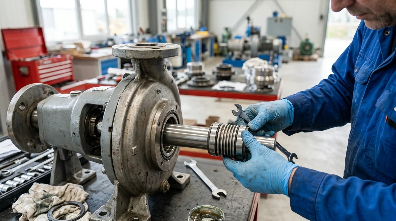
Executing a mechanical seal replacement requires a rigorous engineering approach rather than a simple swap of components. Industrial facilities often treat seal failures as routine maintenance events, but premature or repeated failures indicate an underlying misalignment between the seal’s design and the actual operating conditions. Establishing a definitive baseline of the original seal’s performance is the critical first step before specifying any replacement. Without this diagnostic phase, reliability engineers risk carrying over inherent design flaws into the new installation, thereby perpetuating a cycle of high maintenance costs and compromised equipment availability.
Baseline performance metrics provide the quantitative foundation required to justify alternative designs, materials, or support systems. By analyzing the lifecycle of the original equipment manufacturer (OEM) seal, operators can determine whether the replacement should replicate the existing component or introduce engineered upgrades. This shifts the focus from reactive repair to proactive reliability enhancement, ensuring the new seal meets or exceeds current industrial standards such as API 682.
Define Original Seal Performance
Defining original seal performance requires quantitative tracking of historical reliability data, primarily Mean Time Between Failures (MTBF) and specific emission rates. In heavy process industries, a standard API 682 Category 2 or 3 mechanical seal is typically expected to achieve a minimum MTBF of 36 to 60 months under steady-state conditions. If historical plant data reveals an MTBF of fewer than 12 months, the original seal’s performance is objectively deficient, necessitating a root cause analysis rather than a direct, like-for-like replacement.
Performance baselining also involves quantifying leakage and fugitive emissions. For volatile organic compounds (VOCs), acceptable leakage rates are strictly governed by environmental regulations. Baseline performance must be measured against standards such as EPA Method 21, which often mandates localized emission concentrations below 500 parts per million (ppm). Understanding how the original seal performed against these specific thresholds determines the stringency required for the replacement’s face topography and secondary containment mechanisms.
Identify Common Replacement Risks
Transitioning away from the original seal design without a comprehensive engineering review introduces significant operational risks. One of the most common replacement risks is the alteration of the seal balance ratio or spring compression rates, which can drastically shift the pressure profile across the seal faces. An improper balance ratio can lead to excessive heat generation, vaporization of the fluid film, and subsequent dry running, potentially reducing the seal’s fatigue life substantially.
Furthermore, substituting proprietary OEM elastomers or metallurgy with aftermarket equivalents without verifying chemical compatibility can result in catastrophic failure. Swelling or extrusion of secondary sealing elements, such as O-rings, can cause the dynamic seal face to hang up. Reliability teams must evaluate the risk of thermal shock and mechanical distortion, ensuring that the replacement seal’s structural integrity aligns perfectly with the dynamic characteristics of the pump shaft and stuffing box.
Confirm Business and Operational Drivers
Every mechanical seal replacement must be anchored by clear business and operational drivers to justify the engineering effort and capital expenditure. The primary operational driver is often the reduction of process downtime. In a high-capacity petrochemical refinery, an unplanned pump outage due to a mechanical seal failure can incur massive hourly production losses, making the initial purchase price of the replacement seal mathematically negligible compared to the value of extended uptime.
Business drivers also include energy efficiency and water conservation. A strategic replacement project might be driven by the need to upgrade to advanced gas-lubricated seals or optimize flush plans, thereby meaningfully reducing annual utility consumption. Confirming these drivers ensures the replacement strategy aligns with broader corporate sustainability and profitability targets, rather than just fulfilling a short-term maintenance request.
Technical Criteria for Selecting a Replacement Mechanical Seal
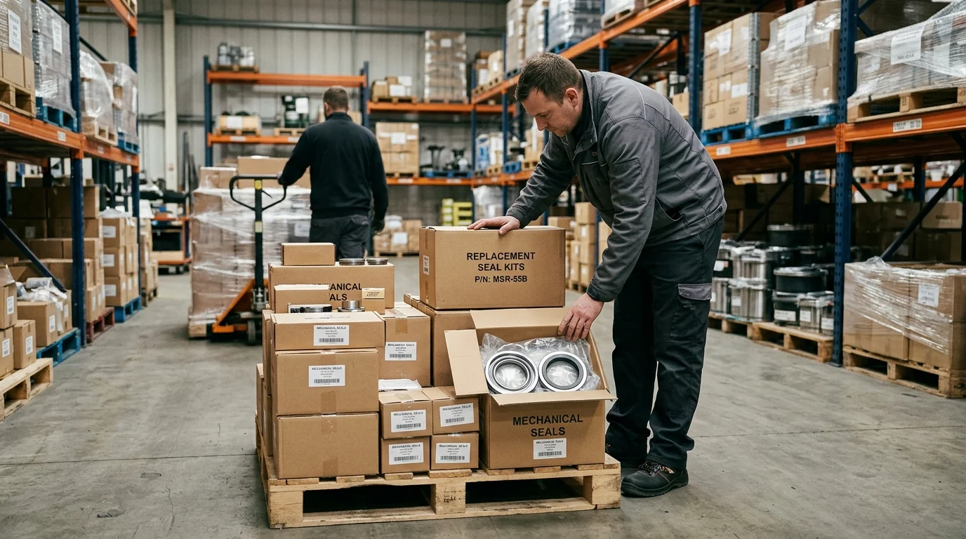
Once baseline performance and operational drivers are established, the focus shifts to the strict technical criteria governing the mechanical seal replacement. Selecting an appropriate seal requires matching the metallurgical and thermodynamic properties of the seal components to the physical realities of the pumping system. A mismatch in any single technical parameter can lead to immediate commissioning failures or severely degraded lifecycle performance.
The technical evaluation must be holistic, encompassing the primary seal faces, secondary elastomeric seals, structural metallurgy, and the geometric constraints of the equipment housing. By treating the mechanical seal as an integrated micro-system, engineers can specify replacements that withstand transient process spikes, variable speed operations, and aggressive chemical environments.
Check Materials, Elastomers, and Metallurgy
The selection of face materials, elastomers, and structural metallurgy dictates the seal’s resistance to wear, chemical attack, and thermal distortion. Primary seal faces typically utilize combinations of Carbon Graphite, Silicon Carbide (SiC), and Tungsten Carbide (TC). Silicon Carbide offers exceptional hardness and thermal conductivity, making it the standard for abrasive applications, while Carbon paired with SiC is preferred for its self-lubricating properties in clean fluids. For secondary seals, elastomer selection is highly temperature and chemical dependent. Standard Fluoroelastomers (FKM) are generally limited to 200°C, whereas Perfluoroelastomers (FFKM) can maintain elasticity in extreme applications up to 327°C.
| Component Category | Typical Material | Max Operating Temp (°C) | Primary Application / Advantage |
|---|---|---|---|
| Primary Face | Silicon Carbide (SiC) | 1,400°C (Material Limit) | High abrasion resistance, excellent thermal conductivity. |
| Mating Face | Carbon Graphite (Resin) | 260°C | Low friction, self-lubricating, forgiving in marginal lubrication. |
| Secondary Elastomer | FKM (Viton™) | 200°C | Broad chemical resistance, standard for water/oil. |
| Secondary Elastomer | FFKM (Kalrez™) | 327°C | Extreme chemical inertness, high-temperature stability. |
| Structural Metal | 316 Stainless Steel | N/A (Yield dependent) | Standard corrosion resistance for glands and springs. |
Structural metallurgy for the gland plate, springs, and drive collar must also be scrutinized. While 316 Stainless Steel is the industry standard, highly corrosive environments involving chlorides or sulfuric acid may necessitate the specification of Duplex Stainless Steels, Alloy 20, or Hastelloy C-276 to prevent stress corrosion cracking and pitting.
Match Pressure, Temperature, Speed, and Fluid Conditions
A successful mechanical seal replacement requires absolute alignment with the process fluid’s Pressure-Velocity (PV) limits, temperature fluctuations, and rheological properties. The PV value represents the severity of the application; standard unbalanced pusher seals are typically restricted to operating pressures up to 10 barg (145 psig), whereas balanced seals can comfortably handle pressures up to 40 barg (580 psig) and shaft speeds up to 25 meters per second (5,000 feet per minute). Exceeding the seal’s designed PV limit destroys the fluid film, causing rapid face vaporization and thermal fracturing.
Fluid conditions such as viscosity, specific gravity, and vapor pressure margin must be meticulously matched. If the process fluid operates within 2°C to 3°C of its vapor pressure, localized frictional heat at the seal faces will induce flashing. In such cases, the replacement seal must integrate enhanced cooling mechanisms, such as an API Plan 11/21 flush or a multipoint injection gland, to maintain a stable liquid film and prevent catastrophic dry running.
Verify Dimensions and Installation Requirements
Dimensional verification is the final, non-negotiable step in the technical selection process. The replacement seal must conform to the geometric constraints of the pump’s stuffing box or seal chamber. For equipment conforming to API 610 and API 682 standards, the seal chamber must provide a minimum radial clearance of 0.125 inches (3.175 mm) between the rotating seal components and the chamber bore to allow adequate fluid circulation and heat dissipation.
Installation requirements also demand strict adherence to shaft tolerances. A mechanical seal replacement will fail prematurely if the equipment exhibits excessive shaft runout, deflection, or end play. Industry standards dictate that shaft runout must not exceed 0.002 inches (0.05 mm) Total Indicator Reading (TIR) at the seal face location, and axial end play must be limited to 0.005 inches (0.13 mm). Verifying these dimensions ensures the new seal operates within its designed spatial envelope, preventing structural fatigue and binding.
How to Compare Mechanical Seal Replacement Options
Comparing mechanical seal replacement options requires an analytical framework that strips away marketing claims and focuses purely on engineering data and lifecycle economics. Facilities are frequently presented with multiple replacement pathways: direct OEM replacements, engineered upgrades from specialized seal manufacturers, or standard aftermarket equivalents. Evaluating these options necessitates a side-by-side comparison of mechanical specifications, projected reliability, and long-term financial impact.
Reliability and procurement teams must collaborate to ensure that the evaluation process does not default to the lowest initial capital cost. Instead, the comparison must weigh the technical robustness of the proposed seal against the specific criticality of the equipment. A structured methodology prevents the introduction of substandard components into highly critical process loops.
Compare Original and Proposed Seal Data
The initial phase of comparison involves a rigorous engineering review of the original seal’s data sheet versus the proposed replacement’s specifications. Key mechanical parameters, such as the seal balance ratio, must be scrutinized. A typical balanced mechanical seal features a balance ratio between 0.65 and 0.75, which optimizes the closing forces on the seal faces to minimize heat generation while preventing leakage. If a proposed replacement alters this ratio, the supplier must provide thermodynamic calculations justifying the change.
Additionally, spring loads and drive mechanisms must be evaluated. Comparing a single large coil spring design against a multiple stationary spring design reveals differing capabilities in handling process fluids laden with suspended solids. Multiple spring designs offer uniform face loading but are susceptible to clogging in viscous fluids, whereas single coil springs are robust but may impart uneven wear over time. The proposed seal data must explicitly address how its mechanical architecture mitigates the specific failure modes experienced by the original seal.
Evaluate Leakage, Reliability, and Service Life
Evaluating projected leakage, reliability, and service life is central to the comparison process. The proposed mechanical seal replacement must offer a quantifiable improvement in MTBF, ideally targeting a minimum service life of 36 months for continuous duty applications. Suppliers should provide empirical data or theoretical wear models demonstrating how their specific face material combinations reduce friction and extend operational life under the plant’s specific fluid conditions.
Leakage control evaluation must account for both normal operational seepage and catastrophic failure containment. For hazardous chemicals, comparing dual seal options is critical. A dual pressurized seal (double seal) utilizing an API Plan 53A system guarantees zero process emissions to the atmosphere, whereas a dual unpressurized seal (tandem seal) allows minor primary face leakage into a containment fluid. The choice directly impacts environmental compliance and site safety profiles.
Separate Purchase Price From Total Cost
Separating the initial purchase price from the Total Life Cycle Cost (LCC) is the most critical financial step in comparing mechanical seal replacement options. The LCC calculation must incorporate the capital cost, installation expenses, energy consumption, barrier fluid maintenance, and the statistical cost of downtime over a projected 5-year operational period. A seal with a lower upfront cost that requires frequent maintenance or causes unexpected outages is mathematically inferior to a premium engineered seal.
| Cost Category | Standard OEM Seal (Option A) | Engineered Upgrade (Option B) | Impact over 5 Years |
|---|---|---|---|
| Initial Purchase | $2,500 | $6,000 | +$3,500 capital outlay for Option B. |
| Installation & Setup | $1,000 | $1,200 | Minor variance due to complexity. |
| Annual Maintenance | $1,500/yr | $400/yr | Option B reduces flush fluid & inspection costs. |
| Unplanned Downtime Cost | $20,000 (1 failure expected) | $2,000 (probabilistic risk) | High risk penalty for Option A. |
| Total 5-Year LCC | $31,000 | $11,200 | Option B yields a $19,800 net saving. |
As demonstrated in the LCC model, a mechanical seal replacement where the initial hardware costs $6,000 can easily outcompete a $2,500 standard seal when factoring in an unplanned downtime penalty. Procurement decisions must be strictly guided by this comprehensive LCC framework rather than isolated departmental budgets.
Replacement Process for Maintenance and Reliability Teams
The physical execution of a mechanical seal replacement bridges the gap between engineering theory and operational reality. For maintenance and reliability teams, the replacement process must be governed by strict procedural controls, quality assurance checks, and precision maintenance practices. A perfectly specified mechanical seal will still fail prematurely if the installation environment is contaminated or if the equipment assembly introduces mechanical stresses.
Establishing a formalized replacement protocol ensures repeatability and traceability across the facility. This protocol must encompass the initial teardown and diagnostic phase, supplier validation, and the final commissioning sequence. By standardizing these procedures, industrial plants can systematically eliminate human error, which remains one of the leading causes of early-life mechanical seal failures.
Perform Failure Analysis and Equipment Inspection
Before installing a new seal, maintenance teams must perform a comprehensive Root Cause Failure Analysis (RCFA) on the extracted seal and conduct a thorough inspection of the pump. Examining the wear tracks, thermal checking, and blistering on the failed seal faces provides undeniable evidence of the operating conditions at the time of failure. For instance, deep concentric grooving on a carbon face strongly indicates the presence of abrasive particulates that were not adequately flushed from the stuffing box.
Simultaneously, the equipment itself must be subjected to precision dimensional checks. Maintenance technicians must use dial indicators to measure shaft concentricity, bearing housing alignment, and seal chamber squareness. If the stuffing box face is not perpendicular to the shaft axis within a tolerance of 0.002 inches (0.05 mm), the stationary gland will distort upon tightening, forcing the seal faces out of parallel alignment and guaranteeing a rapid leakage failure of the replacement seal.
Verify Supplier Capability and Documentation
The mechanical seal replacement process must include a stringent verification of supplier capability and documentation. Reliability teams should ensure that the seal manufacturer operates under a recognized quality management system, such as ISO 9001, and can provide comprehensive Material Test Reports (MTRs) for all wetted metallic components. This documentation is legally and operationally critical when replacing seals in highly corrosive or high-pressure environments.
Furthermore, engineered and high-criticality seals must undergo factory acceptance testing prior to shipment. Verification should include hydrostatic pressure testing of the seal gland assembly at 1.5 times the maximum allowable working pressure (MAWP) to ensure structural integrity and O-ring extrusion resistance. Procuring seals with full dimensional drawings and certified installation manuals is mandatory to prevent discrepancies during the physical assembly on the plant floor.
Control Installation, Commissioning, and Monitoring
Controlling the installation and commissioning phases demands precision maintenance techniques. Installation must be performed in a clean environment, as even microscopic particulate contamination on the lapped seal faces (which are typically lapped to strict industry-standard flatness tolerances, often measured in helium light bands) can initiate leakage. Technicians must strictly follow the manufacturer’s torque specifications and cross-tightening patterns for the gland bolts to prevent uneven compression of the stationary components.
Commissioning requires systematic verification of all supporting seal flush and barrier fluid systems. For dual seals, the barrier fluid pressure must be accurately set—typically 1.5 to 2.0 bar (22 to 29 psi) above the maximum stuffing box pressure—to ensure the fluid film is maintained by the barrier liquid rather than the process fluid. Continuous monitoring of seal chamber temperatures, barrier fluid levels, and localized vibration during the initial 48 hours of operation is critical to validate the success of the mechanical seal replacement.
When Mechanical Seal Replacement Is the Right Decision
Determining the exact timing for a mechanical seal replacement—versus a standard repair—requires strategic alignment with the facility’s broader asset management goals. Triggers for replacement often include MTBF dropping below acceptable plant thresholds, upcoming scheduled turnarounds, or permanent changes in process conditions. Not every seal failure warrants an engineered upgrade, nor is it always cost-effective to repeatedly purchase premium OEM parts for non-critical balance-of-plant (BOP) equipment. The decision must be calculated, risk-based, and heavily reliant on equipment criticality indexing.
Ultimately, the decision to replace, upgrade, or simply repair a mechanical seal defines the maturity of a plant’s reliability culture. By shifting from a reactive replacement strategy to a proactive, reliability-centered maintenance (RCM) approach, organizations can optimize their maintenance spend, reduce inventory overhead, and maximize the operational availability of their rotating equipment.
Choose Between OEM, Engineered, and Standard Seals
The choice between OEM, custom-engineered, and standard aftermarket seals hinges on application severity and warranty status. OEM seals are generally mandated during the initial lifecycle of the equipment to maintain warranty compliance and ensure baseline performance. Facilities must explicitly verify that engineered upgrades do not violate existing OEM warranty requirements or insurance mandates, which often dictate strict adherence to original specifications early in the equipment’s life. However, if an OEM seal consistently fails to meet the minimum MTBF target of 3 years (36 months) due to unique process anomalies, transitioning to a custom-engineered seal designed by a specialized manufacturer becomes the most viable solution to break the failure cycle.
Conversely, for low-criticality applications—such as standard water transfer pumps operating at ambient temperatures and low pressures—standardized aftermarket seals offer a highly cost-effective alternative. These standard seals conform to universal dimensional standards (e.g., EN 12756) and can reduce procurement costs significantly without compromising the acceptable reliability thresholds of non-essential utility systems.
Use a Decision Matrix for Risk and Criticality
Deploying a decision matrix based on risk and criticality ensures that engineering resources and capital are allocated efficiently. Equipment classified under API 610 as highly critical—meaning its failure results in immediate unit shutdown, severe environmental release, or significant safety hazards—demands the highest tier of mechanical seal replacement. In these instances, the matrix dictates the mandatory use of fully engineered, dual-pressurized seals with comprehensive condition monitoring instrumentation.
For medium to low-criticality equipment, the decision matrix balances the cost of the seal against the Mean Time To Repair (MTTR) and redundancy availability. If a redundant pump is readily available and the fluid is non-hazardous (e.g., cooling water), the matrix may justify a lower-tier replacement seal. This systematic categorization prevents the over-engineering of simple applications while ensuring that lethal or highly toxic fluid systems receive the uncompromising technical rigor they require.
Key Takeaways
- Benchmark the original seal’s MTBF, leakage, emissions, and failure history before selecting any replacement design.
- Treat MTBF below 12 months as a warning sign that root cause analysis is needed instead of a direct like-for-like swap.
- Use API 682 expectations, including typical 36 to 60 month MTBF targets, to judge whether the original seal performed adequately.
- Verify seal balance ratio, spring loading, elastomer compatibility, metallurgy, and shaft fit before approving an aftermarket replacement.
- Select replacement mechanical seals based on operating conditions and business goals, not only on dimensional interchangeability or initial purchase price.
Frequently Asked Questions
Why compare a replacement mechanical seal with the original seal?
Comparison shows whether the replacement should duplicate the OEM design or correct reliability, leakage, material, or operating-condition problems that caused poor performance.
What baseline data should be collected before replacing a mechanical seal?
Collect MTBF, leakage rate, emission readings, operating pressure, temperature, speed, fluid properties, failure history, shaft condition, and stuffing box dimensions.
When is a like-for-like seal replacement not recommended?
If the original seal failed repeatedly, had MTBF below expected levels, leaked excessively, or showed material incompatibility, a root cause review and engineered upgrade are better.
What MTBF should an industrial mechanical seal typically achieve?
For API 682 Category 2 or 3 applications, a properly selected seal is often expected to achieve about 36 to 60 months under steady operating conditions.
How can replacement seals reduce fugitive emissions?
Correct face materials, seal balance, secondary containment, and compatible elastomers help keep leakage within regulatory limits, such as EPA Method 21 thresholds.

Post time: Aug-31-2026