


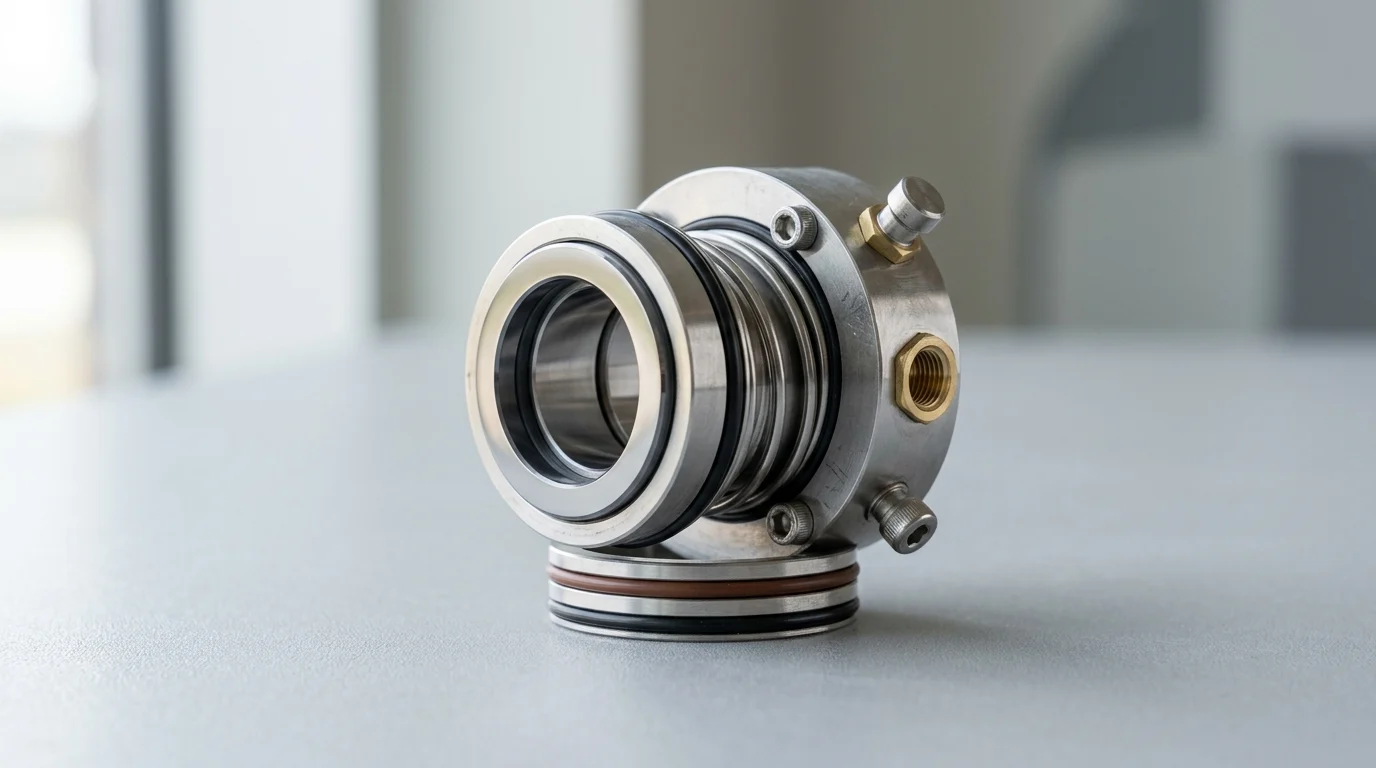
Why Mechanical Seal Reliability Matters in Continuous Operations
In continuous industrial operations—ranging from petrochemical refining and power generation to heavy chemical processing—the integrity of rotating equipment is inextricably linked to fluid containment. The mechanical seal serves as the primary barrier between process fluids and the atmosphere, making its reliability a critical determinant of overall plant availability. When a pump or compressor is designed for uninterrupted operation over multi-year campaigns, the mechanical seal must withstand severe dynamic forces, thermal fluctuations, and chemical attacks without compromising the hydrodynamic fluid film that separates its rotating and stationary faces.
The prevailing standard for continuous-duty rotating equipment, API 682, establishes a baseline expectation of a minimum continuous operating life of 25,000 hours (approximately three years) without replacement. Achieving this mean time between failures (MTBF) requires moving beyond reactive maintenance and adopting a rigorous, engineering-led approach to seal selection, environmental controls, and operational monitoring. A failure in this precision component rarely happens in isolation; it triggers a cascade of operational disruptions that can compromise entire process units.
Defining Reliability Beyond Basic Leak Prevention
Historically, reliability was often equated with the complete absence of leakage. However, modern tribology and seal engineering acknowledge that all mechanical seals require a microscopic fluid film—typically between 0.25 and 1.0 microns thick—to lubricate the faces, meaning minute, imperceptible vapor emissions are intrinsic to their operation. Therefore, reliability in continuous applications is more accurately defined as the stabilization of this fluid film and the predictability of the seal’s lifecycle under designated process conditions.
Unpredictable failures, such as sudden face shattering, elastomer extrusion, or severe blistering, are indicators of systemic unreliability. A reliable mechanical seal degrades in a slow, measurable manner, allowing maintenance personnel to forecast end-of-life and schedule replacements during planned plant turnarounds rather than suffering catastrophic, mid-campaign blowouts.
Production, Safety, and Environmental Impacts
The consequences of mechanical seal failure extend far beyond the direct cost of replacement parts. In high-volume continuous processes, the financial penalty of unplanned downtime is severe; shutting down a critical petrochemical unit due to a primary pump seal failure can incur production losses ranging from $10,000 to over $100,000 per hour. Consequently, seal reliability directly impacts the profitability of the process unit.
Simultaneously, environmental and safety mandates enforce strict operational thresholds. Regulatory frameworks, such as the U.S. Environmental Protection Agency’s (EPA) Method 21, mandate rigorous monitoring of fugitive emissions, often defining a reportable leak as volatile organic compound (VOC) concentrations exceeding 500 parts per million by volume (ppmv). A mechanical seal that fails to maintain emissions below these thresholds not only exposes operators to toxic or flammable hazards but also subjects the facility to substantial regulatory fines and forced curtailments.
Key Design Factors for Continuous-Duty Mechanical Seals
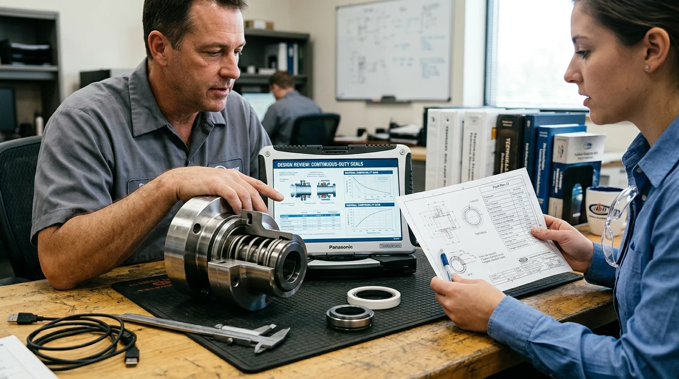
Engineering a mechanical seal for continuous duty requires balancing multiple mechanical and thermodynamic variables. The seal must maintain parallel face topography under fluctuating pressures while dissipating the frictional heat generated by high-speed rotation. Selecting the correct design parameters is a multidisciplinary exercise that dictates the seal’s operational envelope and its resilience against process upsets.
Face Materials, Elastomers, Metallurgy, and Balance Ratio
The selection of face materials fundamentally dictates the wear rate and thermal limits of the seal. In demanding industrial environments, hard-on-hard combinations—such as Silicon Carbide (SiC) running against Silicon Carbide, or SiC against Tungsten Carbide (TC)—are standard due to their exceptional hardness, high thermal conductivity, and resistance to abrasive wear. Elastomeric secondary seals, such as fluoroelastomers (FKM) or perfluoroelastomers (FFKM), must be specified based on chemical compatibility and temperature extremes, with FFKM required for continuous operations exceeding 200°C.
Furthermore, the seal’s balance ratio is a critical geometric calculation. The balance ratio determines the percentage of the seal face area exposed to the closing force of the process fluid. For high-pressure continuous applications, seal balance ratios are typically engineered between 0.65 and 0.85. This reduction in hydraulic closing force minimizes friction and heat generation, allowing balanced seals to effectively manage stuffing box pressures well above 300 psig (20 bar) without vaporizing the fluid film.
Single, Double, and Tandem Seal Configurations
The physical architecture of the seal must align with the hazardous nature of the pumped fluid and the zero-emission requirements of the facility. The choice between single, double, and tandem configurations dictates the level of redundancy and environmental isolation provided by the sealing system.
| Configuration | API Plan Compatibility | Typical Application | Pressure Limit (General) |
|---|---|---|---|
| Single Seal | Plan 11, 21, 32 | Non-hazardous, non-volatile, lubricating fluids | Up to 600 psig (41 bar) |
| Double (Pressurized) | Plan 53A/B/C, 54 | Toxic, abrasive, or zero-emission requirements | Up to 1,200 psig (82 bar) |
| Tandem (Unpressurized) | Plan 52 | Flammable liquids, high vapor pressure fluids | Up to 600 psig primary / 50 psig secondary |
Single seals rely entirely on the process fluid for lubrication, making them suitable only when the fluid is stable and non-hazardous. Double (pressurized dual) seals utilize a barrier fluid maintained at a higher pressure than the process, ensuring that any leakage occurs inward into the pump, absolutely preventing process fluid from escaping. Tandem (unpressurized dual) seals feature a primary seal handling the process pressure and a secondary seal serving as a backup, utilizing a buffer fluid to capture any primary seal vapor leakage.
Seal Support Systems, Flush Plans, and Barrier Fluids
No mechanical seal can achieve continuous-duty reliability without a properly engineered seal support system. These systems, standardized under API 682 piping plans, control the micro-environment within the seal chamber by regulating temperature, pressure, and fluid cleanliness. For instance, an API Plan 11 routes process fluid from the pump discharge back to the seal chamber to provide cooling and flush away particulate matter.
In dual pressurized configurations, the management of the barrier fluid is paramount. Industry standards dictate that the barrier fluid in a Plan 53A or 53B system must be maintained at a pressure of 20 to 30 psi (1.4 to 2.0 bar) above the maximum expected seal chamber pressure. Failure to maintain this differential pressure allows process fluid to contaminate the barrier system, leading to rapid degradation of the inboard seal faces and eventual catastrophic failure of the entire sealing arrangement.
Assessing Operating Conditions and Failure Modes
Industry data consistently demonstrates that over 70% of mechanical seal failures are not caused by inherent defects in the seal design, but rather by deviations in operating conditions or improper equipment installation. Accurately assessing the real-world operational envelope and recognizing specific failure modes are essential for root cause analysis and continuous improvement in plant reliability.
Process Variables That Drive Seal Specification
Process variables dictate the stability of the lubricating fluid film. Temperature, pressure, and fluid viscosity must remain within the seal’s designed operational window. The most critical variable in volatile fluid applications is the vapor pressure margin. To prevent the fluid film from flashing into vapor—which causes immediate dry running and face damage—reliability engineers must ensure the seal chamber pressure is maintained at least 50 psi (3.4 bar) above the fluid’s vapor pressure at the operating temperature.
Additionally, fluctuations in fluid viscosity due to temperature changes can severely impact seal performance. Fluids that polymerize or crystallize when exposed to atmospheric conditions require specialized steam quenches (API Plan 62) to prevent the formation of abrasive solids on the atmospheric side of the seal faces, which would otherwise tear the elastomeric dynamic O-rings and gouge the seal faces.
Failure Patterns Linked to Installation or Operation
Visual inspection of a failed mechanical seal provides a forensic roadmap to the operational upset that caused its demise. Heat checking—characterized by fine radial cracks on the hard seal face—is a definitive indicator of thermal shock, typically resulting from dry running or inadequate flush flow. When a pump loses suction (cavitation) or is run dead-headed, the fluid film evaporates, causing friction to spike temperatures hundreds of degrees in seconds.
Another prevalent failure pattern is coking, where hydrocarbons degrade into hard carbon deposits due to excessive heat in the seal chamber. From an installation standpoint, uneven wear tracks on the seal faces point directly to mechanical misalignment or shaft deflection. If the rotating assembly is improperly balanced or bearing clearances are excessive, the resulting vibration prevents the seal faces from tracking properly, leading to cyclical opening and closing of the gap and rapid particulate ingress.
Operational Data Reliability Teams Should Track
To transition from reactive replacements to predictive maintenance, reliability teams must continuously track specific operational data points surrounding the seal environment. Vibration analysis is critical; overall vibration velocity should be maintained below 0.15 inches per second (3.8 mm/s) RMS to ensure optimal seal life. Spikes in vibration often precede seal failure by several weeks, providing a window for intervention.
Furthermore, monitoring the temperature differential across the seal support system provides immediate insight into seal health. In an API Plan 52 or 53 system, a sudden increase in the temperature of the return line indicates elevated face friction or a failure in the system’s heat exchanger. By integrating barrier fluid pressure, level indicators, and flush flow rates into the plant’s Distributed Control System (DCS), operators can set automated alarms that trigger long before a catastrophic loss of containment occurs.
Practical Steps to Improve Installation and Performance
Translating a highly engineered mechanical seal design into field reliability requires exacting precision during installation and commissioning. The most sophisticated seal will fail prematurely if the rotating equipment housing it does not meet stringent dimensional tolerances. Implementing strict procedural controls during the execution phase is a non-negotiable requirement for continuous operations.
Installation Controls That Reduce Leakage Risk
Precision maintenance standards dictate that the pump or compressor must be fundamentally sound before a seal is introduced. Mechanical seals are not designed to act as bearings; they cannot compensate for bent shafts, degraded bearings, or misaligned housings. To minimize leakage risk, maintenance technicians must verify dimensional tolerances using dial indicators prior to installation.
| Measurement Parameter | Maximum Allowable Tolerance (TIR) | Impact of Exceeding Tolerance |
|---|---|---|
| Radial Shaft Runout | 0.002 inches (0.05 mm) | Fretting of dynamic O-ring, uneven face wear |
| Shaft End Play (Axial) | 0.002 inches (0.05 mm) | Spring fatigue, face separation, blistering |
| Stuffing Box Squareness | 0.0005 in/in of shaft diameter | Stationary face distortion, heavy leakage |
| Bearing Housing Concentricity | 0.005 inches (0.13 mm) | Misalignment, premature bearing and seal failure |
Adhering to these tight tolerances ensures that the seal faces remain parallel and the secondary elastomers are not subjected to excessive dynamic fretting. Furthermore, the use of cartridge seals—which are pre-assembled and pre-set at the factory—has largely eliminated the human error associated with setting the correct spring compression length on the shaft during field installation.
Commissioning Checks for Seal Support Systems
The commissioning phase is a highly vulnerable period for mechanical seals. Improper startup procedures, particularly the failure to adequately vent the seal chamber, account for a significant percentage of early-life failures. Entrapped air or vapor in the stuffing box prevents the liquid flush from reaching the seal faces, resulting in immediate dry running upon equipment startup.
For dual seal support systems, commissioning checks must verify that barrier fluids are filled to the correct level and that accumulators are properly pre-charged. In an API Plan 53B system, for example, the nitrogen bladder pre-charge pressure must be meticulously calculated based on ambient temperature and maximum seal chamber pressure. Operators must strictly follow a sequence of opening suction and discharge valves, establishing flush flow, and verifying barrier pressures before the motor is ever energized.
Monitoring Practices and Spare Parts Strategies
Once operational, sustained reliability relies on structured monitoring and a robust spare parts strategy. Condition-based monitoring utilizing wireless acoustic emission and vibration sensors allows reliability engineers to detect the high-frequency friction indicative of failing fluid films. This real-time data enables the scheduling of maintenance before the seal fails completely, protecting the pump shaft and casing from collateral damage.
From an inventory perspective, maintaining the correct spare parts is critical for minimizing downtime. Engineered mechanical seals, particularly those utilizing specialized metallurgies or custom API 682 configurations, frequently carry lead times of 8 to 12 weeks. Facilities must establish minimum order quantities (MOQs) and strategic stocking levels for critical seals, balancing the carrying cost of inventory against the exorbitant cost of extended unit downtime during an unexpected failure.
Mechanical Seal Sourcing and Lifecycle Decisions
Procuring mechanical seals for continuous industrial operations should never be treated as a transactional commodity purchase. The complexity of the application demands a lifecycle approach to sourcing, where engineering support, material traceability, and total operational costs are weighed far more heavily than the initial acquisition price. Establishing strategic partnerships with seal manufacturers ensures alignment between plant reliability goals and supply chain execution.
Compliance Standards and Documentation Requirements
Industrial seals must comply with rigorous international standards to ensure safety and interoperability. In the oil, gas, and petrochemical sectors, API 682 (ISO 21049) 4th Edition is the definitive standard, dictating everything from seal chamber dimensions to default material selections and testing protocols. Sourcing seals that explicitly meet these standards guarantees a baseline of engineering rigor and tested performance.
Documentation is equally critical. For hazardous environments, seals must often comply with ATEX directives for equipment used in explosive atmospheres. Furthermore, facilities require comprehensive Material Test Reports (MTRs) to verify the metallurgical composition of seal components, ensuring they meet the corrosion allowance requirements for the specific process fluid. A supplier’s inability to provide exhaustive, traceable documentation is a critical disqualifier in high-stakes continuous operations.
Total Cost of Ownership Versus Purchase Price
A common pitfall in procurement is over-indexing on the initial purchase price, which typically represents only 10% to 15% of a mechanical seal’s Total Cost of Ownership (TCO). The true cost of a seal encompasses maintenance labor, barrier fluid consumption, and, crucially, energy consumption. Because mechanical seals rely on friction to maintain the fluid film, they act as a parasitic load on the motor.
A poorly optimized seal can consume 1 to 3 kW of power per pump. In a facility operating hundreds of pumps continuously, the energy penalty of inefficient seals translates to tens of thousands of dollars annually. Furthermore, a seal purchased at a 20% discount that fails every 12 months will vastly exceed the TCO of a premium, engineered seal that reliably operates for the full 25,000-hour API target, factoring in the avoided costs of downtime, labor, and process fluid loss.
Decision Framework for Selecting the Right Seal
Selecting the right seal requires a structured decision framework that balances standardization against application-specific optimization. Standardizing on a limited number of seal types and sizes across a plant reduces inventory complexity and simplifies maintenance training. However, highly aggressive fluids or extreme temperature applications demand highly customized engineered solutions.
Reliability and procurement teams should utilize a weighted decision matrix when evaluating seal upgrades. This matrix must evaluate parameters including fluid toxicity, operating pressure, temperature margins, required MTBF, and the supplier’s local engineering support capabilities. By shifting the sourcing criteria from ‘lowest cost’ to ‘lowest cost per operating hour,’ industrial facilities can secure mechanical sealing solutions that actively protect continuous production and enhance overall plant profitability.
Key Takeaways
- Specify seals against actual pressure, temperature, speed, fluid chemistry, and duty cycle rather than selecting only by pump model.
- Use API 682’s 25,000-hour continuous operating life target as a practical benchmark for critical pump seal reliability.
- Protect the 0.25 to 1.0 micron lubricating film between seal faces by preventing dry running, overheating, and unstable flush conditions.
- Treat leakage trends, vibration, temperature rise, and emissions data as early warnings so seal replacement can be scheduled during planned shutdowns.
- For hazardous or volatile services, consider cartridge or double mechanical seals to improve containment and reduce installation-related risk.
Frequently Asked Questions
What makes a mechanical seal reliable in continuous operation?
Reliability means the seal maintains a stable fluid film, controlled leakage, and predictable wear under specified pressure, temperature, speed, and fluid conditions.
How long should a continuous-duty mechanical seal last?
For API 682-aligned rotating equipment, a common reliability target is at least 25,000 hours, or about three years, of continuous operation without replacement.
Why do mechanical seals need a microscopic fluid film?
A thin film, typically 0.25 to 1.0 microns, lubricates the seal faces, reduces frictional heat, and prevents dry contact that can cause rapid failure.
What are common causes of mechanical seal failure?
Frequent causes include incorrect seal selection, poor installation, dry running, thermal shock, shaft misalignment, vibration, chemical attack, and inadequate flush or cooling plans.
When should a plant consider cartridge or double mechanical seals?
Cartridge seals help reduce installation errors, while double seals are often preferred for hazardous, toxic, volatile, or high-value fluids where containment is critical.

Post time: Sep-06-2026