


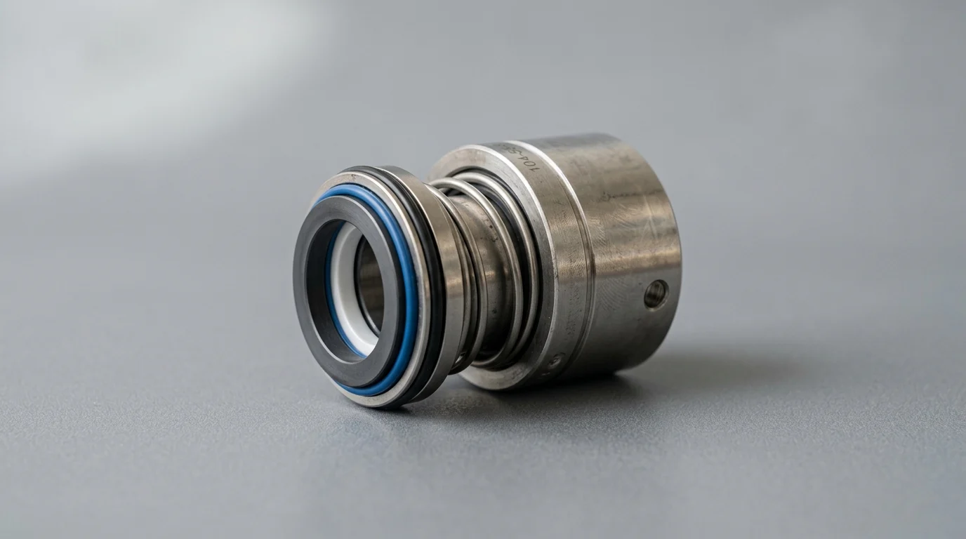
Why Hot Water Pumps Destroy Mechanical Seals
Hot water applications pose uniquely severe challenges for rotating equipment. Above 160°F (71°C), the physical dynamics of water change significantly, decreasing its lubricity and exponentially increasing the likelihood of fluid flashing at the sealing interface. Understanding why a mechanical seal fails in these environments requires differentiating between normal mechanical wear and accelerated destruction caused by thermal or hydraulic instability.
When standard utility pumps are repurposed for high-temperature boiler feed, condensate return, or district heating applications, their sealing mechanisms are frequently pushed beyond their design limits. Mitigating these failures requires a deep understanding of the thermodynamic forces acting on the seal chamber and the specific failure modes they induce.
Common signs of repeated seal failure
Visual and operational indicators of premature failure often present long before a catastrophic leak forces a pump shutdown. Maintenance personnel may observe carbon dust accumulation around the gland, intermittent weeping during startup, or a gradual increase in seal water consumption if an external flush is utilized. When the Mean Time Between Failures (MTBF) for a mechanical seal drops below 12 to 18 months in a standard hot water application, it strongly indicates chronic environmental or systemic issues rather than isolated component defects.
Evaluating the timeline of the failure is equally critical. A seal that fails within 48 hours of installation typically points to severe installation errors, gross misalignment, or immediate dry-running conditions. Conversely, failures occurring after three to six months of operation are more likely linked to fluctuating process conditions, gradual scale buildup, or sustained operation outside the optimal thermal envelope.
Effects of temperature, pressure, and vapor margin
The relationship between temperature, pressure, and vapor margin is the single most critical factor in hot water seal reliability. As water temperature rises, its vapor pressure increases exponentially. If the pressure inside the seal chamber does not exceed the water’s vapor pressure by an adequate margin—typically recommended to be at least 25 to 50 psi (1.7 to 3.4 bar) above vapor pressure—flashing occurs.
Flashing is the rapid phase change of liquid water to steam directly between the mechanical seal faces. Because steam provides virtually zero lubricity, the faces experience immediate dry running, generating massive friction and localized heat. This thermal spike causes the faces to distort, opening the fluid film gap and allowing abrasive particulates to enter, which rapidly accelerates the destruction of the lapped surfaces.
Seal failure versus system failure symptoms
Accurate diagnosis requires distinguishing between a primary seal failure and a systemic pump failure that merely manifests at the seal. A mechanical seal is often the weakest link in a rotating assembly and will fail as a secondary symptom of broader hydraulic or mechanical distress. For example, cavitation caused by inadequate Net Positive Suction Head available (NPSHa) creates violent pressure pulsations that can shatter brittle seal faces.
Similarly, bearing degradation or operation away from the pump’s Best Efficiency Point (BEP) generates excessive radial loads. If shaft deflection exceeds 0.002 inches (0.05 mm) at the seal faces, the dynamic tracking capability of the springs is overwhelmed. In these scenarios, replacing the mechanical seal without addressing the underlying bearing wear or hydraulic instability guarantees a rapid recurrence of the failure.
Seal Design Factors That Matter Most
Selecting the correct mechanical seal for hot water requires moving beyond standard utility specifications. The physical construction, face geometry, and material composition must withstand both the high-temperature environment and the inherently poor lubricating properties of hot water.
Engineers must evaluate the exact operating parameters—specifically the maximum continuous temperature, transient pressure spikes, and fluid purity—to specify a seal architecture that maintains a stable, liquid fluid film under all anticipated operating conditions.
Balanced versus unbalanced seal designs
The hydraulic balance of a mechanical seal dictates how much fluid pressure is utilized to push the seal faces together. Unbalanced seals are typically limited to pressures around 150 psi (10 bar) and moderate temperatures. In hot water applications, the high closing forces of an unbalanced seal generate excessive frictional heat, which drastically reduces the vapor margin and triggers flashing.
For hot water systems operating above 200°F (93°C) or at elevated pressures, balanced mechanical seals are mandatory. A balanced design alters the geometric ratio of the seal faces, reducing the hydraulic closing force while maintaining enough pressure to prevent leakage. This modification typically lowers heat generation at the faces by 20% to 30%, expanding the pressure-velocity (PV) limit and significantly extending the seal’s operational lifespan in volatile fluids.
Single versus double mechanical seals
Single mechanical seals rely entirely on the pumped process fluid for lubrication and cooling. While cost-effective, they are highly vulnerable to process upsets, flashing, and dry running. If the hot water supply is interrupted or vaporizes, a single seal will fail rapidly. To mitigate this, facilities often transition to double (dual) mechanical seals for critical or high-temperature assets.
Double mechanical seals utilize a secondary barrier or buffer fluid to separate the seal faces from the harsh process fluid, ensuring continuous lubrication regardless of the pump’s internal conditions.
| Configuration | Cooling Requirements | MTBF Expectation | Relative Cost Factor |
|---|---|---|---|
| Single Unbalanced | Minimal (Process fluid) | < 12 months | 1.0x |
| Single Balanced | Moderate (Plan 11/21) | 18 – 24 months | 1.5x |
| Double Unpressurized | High (Plan 52) | 24 – 36 months | 2.5x |
| Double Pressurized | High (Plan 53A/54) | > 36 months | 3.5x |
Face materials, elastomers, and spring selection
Material selection is unforgiving in hot water environments. For the primary seal faces, Antimony-impregnated carbon running against Silicon Carbide (SiC) or Tungsten Carbide (TC) is a common pairing, offering a good balance of wear resistance and dry-running survivability. While SiC versus SiC provides exceptional hardness, it is highly susceptible to catastrophic shattering if the fluid flashes and the faces run dry.
Elastomer (O-ring) selection is equally critical due to the risk of chemical degradation. FKM (Viton) is widely used in industry but is notorious for undergoing hydrolysis—a chemical breakdown—in hot water applications above 212°F (100°C). Instead, EPDM (Ethylene Propylene Diene Monomer) is the preferred elastomer for hot water and steam, reliably handling temperatures up to 300°F (149°C). Additionally, stationary multi-spring designs or metal bellows are recommended over single-coil springs, as they resist clogging from the mineral scale buildup common in hot water systems.
How to Diagnose Seal Failure Before Replacement
Blindly replacing a failed mechanical seal without identifying the root cause guarantees a repeat failure. A methodical teardown and inspection protocol is essential for identifying the specific mechanical, thermal, or chemical stressors that compromised the sealing mechanism.
By treating the failed seal as forensic evidence, reliability engineers can map physical damage patterns back to specific operational anomalies, enabling targeted and effective corrective actions.
Inspecting seal faces, sleeves, and O-rings
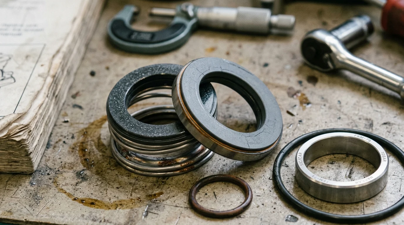
A rigorous teardown inspection provides the most definitive evidence of why a mechanical seal failed. Engineers must examine the primary hard faces for heat checking—a series of fine radial cracks originating from the center of the seal ring. This specific damage pattern is the hallmark of thermal shock, confirming that the fluid flashed to vapor and the faces ran dry before being suddenly quenched by cooler liquid. Additionally, deep grooving or blistering on a carbon primary ring suggests chronic poor lubrication or chemical attack.
Secondary sealing elements and hardware also tell a crucial story. O-rings that appear extruded, flattened, or brittle indicate temperature excursions well beyond the elastomer’s rated limits. For instance, if an EPDM O-ring is exposed to localized temperatures exceeding 300°F (149°C), it will harden and lose its elasticity, leading to a secondary leak path. Fretting on the pump shaft or sleeve under the dynamic O-ring further points to excessive axial movement or vibration during operation.
Checking alignment, vibration, and pipe strain
The mechanical integrity of the pump directly dictates the lifespan of the seal. Precision alignment between the pump and motor is non-negotiable. Angular misalignment exceeding 0.005 inches per inch, or parallel misalignment beyond 0.002 inches, forces the mechanical seal to compensate dynamically with every shaft rotation, leading to rapid fatigue of the springs or bellows and excessive face wear.
Pipe strain is another hidden killer of mechanical seals. When heavy, thermally expanded hot water piping is bolted to the pump flanges without proper support, it distorts the pump casing. This distortion creates severe shaft deflection and internal rubbing. Conducting a vibration analysis is a standard diagnostic step; overall vibration exceeding 0.15 in/sec RMS often reveals bearing wear, imbalance, or resonance issues that are actively degrading the seal’s micro-inch face tracking capability.
Reviewing operating data and process conditions
Physical inspection must be correlated with operational data to form a complete diagnostic picture. Reliability teams should review SCADA or DCS historical trends leading up to the failure. Look for sudden pressure spikes, dead-heading events, or temperature surges that align with the physical damage observed on the seal.
Particular attention must be paid to flow rates. If the pump frequently operates below its Minimum Continuous Safe Flow (MCSF), the internal fluid recirculation acts as a hydraulic brake, rapidly transferring kinetic energy into heat. In an enclosed volute, this can cause fluid temperatures to surge by 10°F to 20°F (5°C to 11°C) per minute, vaporizing the water at the seal interface long before the bulk fluid temperature triggers a high-heat alarm.
Corrective Actions to Prevent Recurring Failures
Mitigating repeated failures requires altering the operating environment or the mechanical seal support system to ensure stable, cool, and clean fluid remains at the seal faces at all times.
Corrective actions range from enforcing stricter maintenance and operational procedures to implementing advanced API piping plans that actively manipulate the thermodynamics of the seal chamber.
Improving installation and seal chamber preparation
The foundation of seal reliability is established before the pump is even turned on. Proper installation tolerances must be verified using dial indicators. Shaft runout must be strictly maintained at less than 0.001 inches (0.025 mm) Total Indicator Reading (TIR). Furthermore, the seal chamber face runout (squareness to the shaft) must be within 0.0005 inches per inch of shaft diameter to ensure the stationary gland sits perfectly flush.
Seal chamber preparation also includes rigorous venting procedures. Hot water systems are prone to trapped air or vapor pockets in the upper quadrant of the stuffing box. If the seal chamber is not properly vented prior to startup, the upper portion of the seal faces will run completely dry, causing immediate thermal damage within the first few seconds of operation.
Controlling minimum flow and startup procedures
Operational discipline is just as critical as mechanical design. To prevent the rapid temperature spikes associated with low-flow recirculation, facilities must implement mechanical or procedural safeguards to guarantee the pump never operates below its MCSF. Installing Automatic Recirculation Valves (ARVs) or dedicated minimum flow bypass lines ensures a continuous volume of fluid moves through the casing, dissipating heat effectively.
Startup protocols must also be strictly enforced, particularly for standby pumps in hot water service. Subjecting a cold pump casing to an immediate influx of 250°F (121°C) water causes severe, asymmetric thermal distortion, misaligning the seal faces before the shaft even begins to rotate. Facilities must establish controlled warm-up procedures, utilizing casing drains or warm-up lines to maintain a gradual heating rate of approximately 5°F to 10°F per minute, ensuring thermal equilibrium prior to startup.
Using flush, quench, cooling, or barrier systems
When the process temperature inherently exceeds the safe operating limits of the seal, external environmental controls are required. API Piping Plans dictate how fluid is routed to and from the mechanical seal to provide cooling, flushing, or barrier protection.
| API Piping Plan | Mechanism | Best Hot Water Use Case | Typical Temp Reduction |
|---|---|---|---|
| Plan 11 | Discharge bypass to seal | Basic flushing, < 180°F | Minimal (Prevents stagnation) |
| Plan 21 | Cooled discharge bypass | Moderate temps, 180°F – 200°F | 20°F – 40°F |
| Plan 23 | Closed loop seal cooler | High temps, > 200°F | 50°F – 100°F |
| Plan 32 | External clean flush | High particulate/scale present | Dependent on flush source |
For severe hot water applications, API Plan 23 is highly recommended. Unlike Plan 21, which continuously cools hot fluid from the pump discharge, Plan 23 recirculates a small volume of fluid locally between the seal chamber and a dedicated heat exchanger. This highly efficient closed-loop system can easily reduce seal chamber temperatures by 50°F to 100°F (28°C to 56°C) compared to the bulk process temperature, completely eliminating the risk of flashing and exponentially increasing seal life.
Repair, Upgrade, or Redesign Decision
When confronted with chronic mechanical seal failures, maintenance and reliability engineering teams must evaluate whether to continue repairing the existing configuration, upgrade the seal specifications, or pursue a comprehensive system redesign.
This decision hinges on a rigorous lifecycle cost analysis, balancing upfront capital expenditures against the long-term penalties of maintenance labor, replacement parts, and unplanned production downtime.
Comparing repair cost and seal life
The true cost of a mechanical seal failure extends far beyond the invoice for the replacement part. It encompasses the labor required for teardown and installation, the cost of barrier fluids, the environmental impact of leaks, and the massive financial penalty of lost production. A standard repair-in-kind approach is often a false economy in chronic failure scenarios.
For example, if a standard utility seal costs $1,500 to repair but fails every 6 months, the annualized direct maintenance cost exceeds $3,000—not including downtime. This recurring expense quickly eclipses the one-time $4,500 to $6,000 investment required for a specialized, high-temperature cartridge seal equipped with an optimized piping plan that delivers a reliable 36-month MTBF. Evaluating the Total Cost of Ownership (TCO) over a three- to five-year horizon clearly dictates when a repair strategy is no longer viable.
When to upgrade seal specifications
Upgrading seal specifications becomes necessary when the operational realities of the pump diverge from its original design criteria. A common trigger for an upgrade is process creep, where system modifications gradually push the water temperature above the original design spec (e.g., creeping from an initial 180°F to a sustained 220°F over several years of facility expansion).
Other triggers include frequent on/off cycling of the pump, which induces repetitive thermal shock, or the implementation of stricter environmental and safety regulations regarding fluid leakage. Moving from a single unbalanced component seal to a balanced cartridge seal, transitioning from FKM to EPDM elastomers, or upgrading from a Plan 11 to a Plan 23 cooling loop are standard, highly effective specification upgrades for hot water applications exceeding the 200°F (93°C) threshold.
Building a prioritized corrective action plan
Resolving repeated failures requires a phased, prioritized corrective action plan rather than a scattershot approach. Phase one should focus on the low-hanging fruit: correcting pump alignment, verifying NPSHa margins, eliminating pipe strain, and strictly enforcing pump warm-up and minimum flow procedures. These operational corrections require minimal capital expenditure and often resolve a significant percentage of premature failures.
Phase two involves engineering upgrades to the seal itself, such as specifying balanced face geometries, optimizing face materials for poor lubricity, and ensuring elastomer compatibility. Finally, phase three requires capital expenditure for advanced support systems, such as installing seal coolers (Plan 23) or transitioning to dual pressurized seal configurations (Plan 53A) for the most aggressive, high-temperature applications. This systematic escalation ensures that capital is deployed efficiently to permanently eliminate the root cause of the mechanical seal destruction.
Key Takeaways
- Maintain seal chamber pressure at least 25 to 50 psi above water vapor pressure to reduce flashing and dry running at the seal faces.
- Treat MTBF below 12 to 18 months in hot water service as evidence of a chronic system or application problem, not just a bad seal.
- Investigate failures within 48 hours for installation errors, gross misalignment, incorrect setting, or immediate dry-running conditions.
- Check pump operating conditions such as NPSH, cavitation, bearing health, shaft deflection, and distance from BEP before blaming the seal alone.
- Use seal designs, materials, and support plans rated for high-temperature water instead of repurposing standard utility pump seals beyond their limits.
Frequently Asked Questions
Why do mechanical seals fail so often in hot water pumps?
Hot water has lower lubricity and higher vapor pressure. If seal chamber pressure is too close to vapor pressure, water can flash into steam at the seal faces, causing dry running, heat distortion, carbon dust, leakage, and rapid face damage.
What vapor margin is recommended for hot water mechanical seals?
A practical target is keeping seal chamber pressure at least 25 to 50 psi, or 1.7 to 3.4 bar, above the water vapor pressure. This margin helps prevent flashing at the seal faces.
Does a leaking seal always mean the seal was defective?
No. The seal is often the first component to show symptoms of a wider system problem, such as cavitation, poor NPSH, shaft deflection, bearing wear, misalignment, or operation far from the pump’s Best Efficiency Point.
What does seal failure within 48 hours usually indicate?
Failure within 48 hours usually points to installation error, severe misalignment, incorrect seal setting, immediate dry running, or a major operating condition that the seal cannot survive.
When should repeated seal failure be treated as a chronic issue?
If mechanical seal MTBF falls below 12 to 18 months in a standard hot water service, the cause is likely systemic rather than random. Review pressure, temperature, flush plan, pump hydraulics, installation, and shaft condition.

Post time: Jul-21-2026