


Why API 682 Mechanical Seals Matter Strategically
The American Petroleum Institute’s API 682 standard (currently in its Fourth Edition) serves as the definitive global benchmark for designing, testing, and applying mechanical seals in the petroleum, natural gas, and chemical industries. The shift to the Fourth Edition introduced updated clearance defaults, revised qualification testing protocols, and new piping plans, making it crucial for engineers managing legacy specifications or mixed fleets to understand these modern requirements. Unlike general-purpose industrial sealing guidelines, API 682 provides a rigorous, standardized framework intended to maximize equipment availability and mitigate catastrophic environmental releases. The standard applies to shaft diameters ranging from 20 mm to 110 mm (0.75 to 4.3 inches) and addresses the complex sealing requirements of centrifugal and rotary pumps operating in highly volatile or hazardous conditions.
However, engineers should note that API 682 is not universally mandatory. Local environmental regulations, company-specific engineering standards, and distinct contractual requirements often supersede or modify API 682 defaults.
Selecting a mechanical seal under this standard requires engineers to align mechanical design, metallurgy, and fluid dynamics. Because seal failures account for a significant majority of all centrifugal pump maintenance events, following API 682 protocols helps facilities manage critical risks. By mandating specific qualification tests, default material selections, and standardized support systems, API 682 eliminates much of the guesswork inherent in custom seal engineering.
Safety and reliability impact
API 682 primarily aims to ensure a high probability of achieving at least three years (approximately 25,000 hours) of continuous operation before requiring maintenance or replacement. Note that this Mean Time Between Failures (MTBF) target is a design intent validated by qualification testing, not an operational warranty; field-achievable performance depends heavily on actual operating conditions and maintenance practices. This design target aligns with the standard turnaround schedules of major refineries and petrochemical complexes, ensuring that pump maintenance does not dictate plant-wide shutdown intervals.
Beyond mechanical reliability, API 682 strictly regulates environmental containment. Facilities must ensure modern mechanical seals comply with stringent localized emissions regulations, such as the EPA’s requirement to maintain Volatile Organic Compound (VOC) emissions below 500 parts per million by volume (ppmv). By utilizing standardized dual-seal arrangements and specific barrier fluid systems, API 682-compliant seals provide the necessary redundancy to capture fugitive emissions. This protects site personnel from hazardous exposure and shields operators from severe regulatory penalties.
Technical and commercial risks
Using pumps in critical hydrocarbon service introduces significant technical and commercial risks. Technically, an incorrectly specified seal can suffer from face vaporization, blistering, or thermal distortion, which leads to a sudden and catastrophic loss of containment. When pumps handle fluids near their boiling points, even minor pressure fluctuations in the seal chamber can induce dry running conditions and destroy the seal faces in a matter of minutes.
Commercially, the risks of non-compliance or poor selection are equally severe. Unplanned downtime in a high-capacity refining unit can incur massive daily financial losses in deferred production. Furthermore, the collateral damage caused by a primary seal failure—such as bearing contamination, shaft scoring, or localized fires—significantly increases repair costs. Investing in a fully compliant API 682 sealing system reduces the risk of these high-stakes financial and operational liabilities.
What to Define Before Selecting API 682 Seals

Before navigating the complexities of seal geometry or material science, engineers must conduct a comprehensive audit of the pump’s operating environment. API 682 uses a precise classification system that dictates the minimum design requirements based on the severity of the application. Failing to accurately define the boundary conditions prior to selection often results in over-engineering, which unnecessarily inflates capital expenditures, or under-engineering, which critically compromises safety.
Pump, fluid, temperature, and pressure conditions
The foundational step in API 682 selection involves mapping the precise fluid properties and thermodynamic conditions within the seal chamber. Engineers must define the fluid’s specific gravity, dynamic viscosity, toxicity, and vapor pressure at the operating temperature. A critical metric in this phase is the vapor pressure margin; a common industry rule of thumb often references maintaining a seal chamber pressure of at least 3.5 bar (50 psi) or a 10% margin above the fluid’s vapor pressure to prevent flashing across the seal faces. However, specific margin requirements vary by API edition, fluid properties, and seal design.
Temperature and pressure boundaries further dictate the mechanical constraints. API 682 categorizes applications across a broad thermal spectrum, typically from -40°C to 400°C (-40°F to 750°F), and accommodates dynamic sealing pressures up to 42 bar (600 psi). Engineers must also document transients, such as startup temperature spikes or temporary loss of suction pressure, because mechanical seals are highly sensitive to sudden thermal shocks and pressure reversals.
Seal categories, types, and arrangements
API 682 organizes mechanical seals into three distinct Categories, three Types, and three Arrangements. The Category designation aligns the seal with the pump type and the operational severity.
| API 682 Category | Pump Standard | Typical Temperature Range | Shaft Size Range | Application Focus |
|---|---|---|---|---|
| Category 1 | Non-API 610 (e.g., ASME B73.1) | -40°C to 260°C | 20 mm to 110 mm | General duty, moderate temperatures, chemical processing. |
| Category 2 | API 610 Heavy Duty | -40°C to 400°C | 20 mm to 110 mm | Refinery applications, higher pressures, standard testing. |
| Category 3 | API 610 Heavy Duty | -40°C to 400°C | 20 mm to 110 mm | Most demanding services, rigorous qualification, strict documentation. |
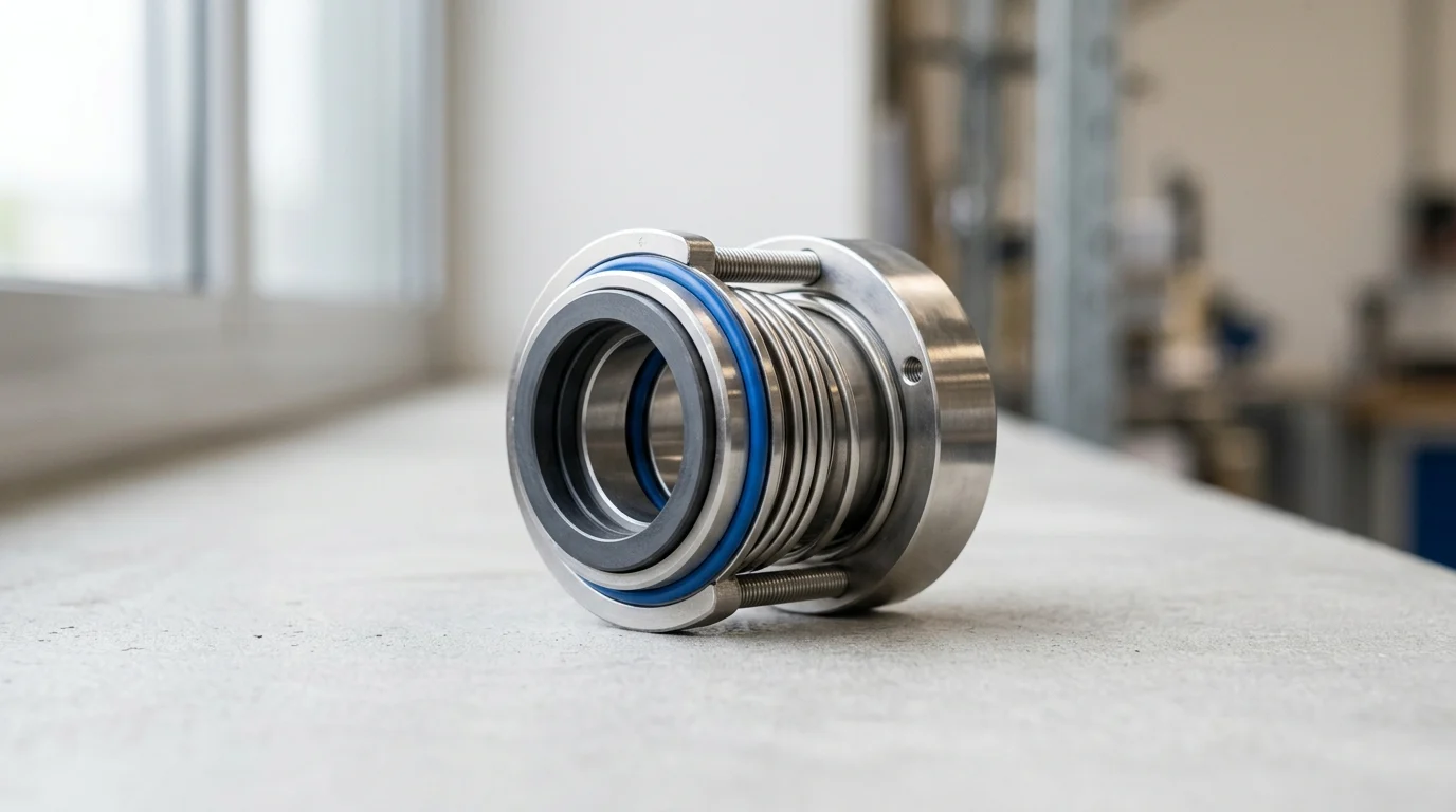
Following the Category, engineers must select the seal Type. Type A refers to balanced, inside-mounted pusher seals utilizing O-rings, which serve as the industry standard for most applications. Type B designates metal bellows seals equipped with elastomer secondary seals, which perform best for fluids that tend to crystallize or foul sliding O-rings. Type C encompasses high-temperature metal bellows seals utilizing flexible graphite secondary seals. Manufacturers engineer Type C specifically for extreme thermal applications exceeding 260°C (500°F) where standard elastomers would rapidly degrade.
Single, dual pressurized, and dual unpressurized options
The Arrangement defines the level of redundancy and emissions control. Arrangement 1 consists of a single seal per cartridge. Engineers specify this for non-hazardous, non-flammable fluids where a minor degree of operational leakage remains acceptable and does not pose an environmental or safety threat.
Arrangement 2 utilizes a dual unpressurized seal configuration. In this setup, the outer seal acts as a containment backup for the primary inner seal. Operators fill the cavity between the seals with a buffer fluid maintained at a pressure lower than the seal chamber.
Arrangement 3 features a dual pressurized seal configuration, utilizing a barrier fluid maintained at a higher pressure than the process fluid. This ensures that any leakage across the inner seal faces consists of the clean barrier fluid entering the process, rather than the hazardous process fluid escaping to the atmosphere. While mandatory for highly toxic or lethal services, engineers must account for operational constraints: barrier fluid leakage into the process can cause product contamination, and support systems like Plan 53A require ongoing verification of nitrogen availability. (Note that Plans 53B, 53C, and 54 offer valid, and sometimes preferable, pressurized alternatives depending on site utilities).
How to Compare API 682 Seal Designs
Once engineers establish the foundational parameters—Category, Type, and Arrangement—the selection process shifts to comparative design evaluation. This phase requires analyzing how different mechanical configurations, material pairings, and auxiliary support systems will interact under the specified operating conditions. A robust comparison evaluates not just the theoretical capability of the seal, but its practical resilience against off-design excursions. It is also important to recognize the qualification gap: comparison criteria apply differently across Categories, as Category 3 seals undergo far more rigorous baseline testing than Category 1 or 2 general-duty seals.
Seal arrangement comparison criteria
When comparing seal arrangements, engineers must prioritize differential pressure capabilities and face loading dynamics. For example, when evaluating an Arrangement 3 dual pressurized seal, the team must account for the barrier fluid pressure requirement. The barrier system must maintain a pressure of at least 1.4 bar (20 psi) above the maximum seal chamber pressure. This constant positive differential ensures zero process emissions but places continuous high-pressure stress on the outboard seal faces.
Another comparative criterion is the tolerance for reverse pressure. During transient conditions or support system failures, a dual seal might experience a reversal of its intended pressure differential. Evaluating how a specific pusher or bellows design handles reverse pressure—such as whether the seal faces remain closed or if the internal components are susceptible to dislodgement—is critical for maintaining containment during upset conditions.
Face materials, elastomers, and metallurgy
The tribological pairing of the seal faces dictates the wear rate, heat generation, and chemical compatibility of the system. The API 682 default pairing for many services is premium resin-impregnated blister-resistant carbon graphite running against reaction-bonded Silicon Carbide (SiC). This pairing offers excellent lubricity and survivability during brief dry-running events. However, for highly abrasive fluids, engineers must specify a hard-on-hard combination, such as sintered SiC against sintered SiC or Tungsten Carbide, to prevent rapid face grooving.
Secondary sealing elements (elastomers) are equally critical and often form the weakest link in the thermal chain. Fluoroelastomers (FKM) act as the standard choice but generally limit continuous operating temperatures to 200°C (392°F). For more aggressive chemicals or higher temperatures, engineers utilize Perfluoroelastomers (FFKM), which push the thermal limit up to approximately 320°C (608°F). Evaluating the swell characteristics and explosive decompression resistance of these elastomers is a mandatory step in the material selection matrix.
API piping plans and support systems
A mechanical seal cannot function reliably without an appropriately matched API piping plan to control the environment around the seal faces. These plans dictate how operators route, cool, and filter flush fluid, buffer fluid, or barrier fluid.
| API Piping Plan | Configuration Type | Primary Function | Typical Application |
|---|---|---|---|
| Plan 11 | Process Flush | Routes fluid from pump discharge to seal chamber. | Standard single seals in clean, moderate-temperature services. |
| Plan 21 | Cooled Process Flush | Routes discharge fluid through a cooler to seal chamber. | Hot services where vapor margin must be increased. |
| Plan 52 | Unpressurized Buffer | Circulates buffer fluid from an external reservoir. | Arrangement 2 dual seals requiring emissions containment. |
| Plan 53A | Pressurized Barrier | Supplies pressurized barrier fluid from a gas-charged reservoir. | Arrangement 3 dual seals in hazardous or toxic services. |
When selecting from the options in the table above, engineers must analyze utility constraints and maintenance burdens alongside the application requirements. For instance, while a Plan 11 process flush works well for standard single seals, hazardous services require a pressurized barrier. If choosing Plan 53A for this barrier, the facility must supply reliable nitrogen to maintain pressure and continuously verify its availability. Alternatively, Plans 53B (bladder accumulator) and 53C (piston accumulator) eliminate the need for a continuous nitrogen supply, while a Plan 54 system utilizes a centralized, standalone barrier fluid pumping skid. The choice between a localized reservoir (53A/B/C) and a centralized system (54) depends heavily on the plant’s existing infrastructure, the number of pumps in the unit, and the acceptable footprint for auxiliary skids.
How to Specify, Source, and Install Mechanical Seals
Transitioning from theoretical selection to physical implementation requires meticulous specification, rigorous supplier vetting, and precise installation protocols. Even the most perfectly engineered API 682 seal will fail prematurely if the procurement documentation is ambiguous or if the mechanical execution on the shop floor or field site falls short of API tolerances.
Building an API 682 seal specification
Building a robust API 682 seal specification begins with completing the standardized API data sheets. Engineers must explicitly detail the process fluid properties, the selected Category, Type, and Arrangement, the material codes, and the required piping plans. Ambiguity in the data sheet often leads manufacturers to make default selections that may not align with the plant’s specific operational nuances or localized safety standards. Because manufacturers may interpret standard provisions differently, the completed data sheet serves as the definitive contractual and technical guide, overriding any generic standard defaults.
The specification must also define acceptable mechanical tolerances for the pump itself, as the seal relies on the structural rigidity of the rotating equipment. Specifications should mandate that the pump shaft radial runout does not exceed 0.05 mm (0.002 inches) Total Indicator Reading (TIR) at the seal faces, and that the seal chamber face perpendicularity remains within 0.5 micrometers per millimeter of seal chamber bore. Enforcing these tolerances ensures the seal will not suffer from excessive dynamic distortion.
Supplier qualification and documentation
API 682 requires highly stringent supplier qualification. Purchasers must require prospective vendors to provide documented proof of API 682 qualification testing for the specific seal family being proposed. This testing involves subjecting the seal design to dynamic pressure phases, thermal cycles, and simulated upset conditions to verify the baseline reliability target. Buyers should disqualify suppliers unable to produce valid qualification certificates from critical service bids.
In addition to qualification testing, the procurement phase must account for documentation and delivery logistics. For Category 3 seals, requirements typically include EN 10204 3.1 material certificates for pressure-retaining components, dynamic balancing reports, and certified general arrangement drawings. Buyers must also factor in lead times; while facilities can source standard Category 1 seals in 4 to 8 weeks, highly engineered Category 3 seals with custom metallurgy and Plan 53/54 support systems typically require 12 to 20 weeks.
Installation, flushing, and commissioning
Installation and commissioning pose the final, critical hurdles. Manufacturers deliver API 682 seals as pre-assembled, pressure-tested cartridges. The installation protocol must strictly prohibit technicians from dismantling the cartridge prior to installation. Technicians must adhere to precise torque specifications for gland bolting to prevent uneven compression of the gland gasket, which can distort the stationary seal face and induce immediate leakage.
Commissioning requires systematic venting and fluid management. For dual seals, operators must fill the barrier or buffer fluid system, vent all trapped air, and pressurize the system before introducing the primary process fluid to the pump. If a dual seal runs dry, even for a few seconds during motor rotation checks, the faces will suffer irreversible thermal damage. Proper commissioning also involves verifying that cooling water flow to heat exchangers (e.g., in Plan 21 or Plan 53 systems) meets the specified volumetric flow rates to maintain the thermal equilibrium of the seal chamber.
How to Finalize Seal Selection for Long-Term Value
Finalizing the selection of an API 682 mechanical seal requires engineers to expand their analytical focus beyond immediate capital expenditure (CAPEX) to encompass the Total Cost of Ownership (TCO). The selection process should evaluate long-term operational efficiencies, spare parts management, and the historical reliability of similar installations to ensure the chosen sealing system delivers sustained economic and mechanical value.
Lifecycle cost versus purchase price
When evaluating lifecycle costs, the initial purchase price of an API 682 seal and its support system typically represents only an illustrative 15% to 20% of the total 10-year TCO, according to general industry practice. Facilities accumulate the overwhelming majority of the cost through operational expenditures, including maintenance labor, barrier fluid consumption, and the energy losses associated with friction at the seal faces and the operation of auxiliary cooling systems.
For example, opting for a less expensive single seal (Arrangement 1) with a Plan 32 external flush might save capital upfront. However, if the flush fluid must be continuously injected into the process, the downstream costs of separating or evaporating that flush fluid can be astronomical. Conversely, investing in a more expensive dual pressurized seal (Arrangement 3) with a closed-loop Plan 53A system requires higher initial CAPEX but virtually eliminates product dilution and ongoing flush fluid costs, yielding a significantly lower TCO over the equipment’s lifespan.
Failure history, standardization, and spare parts
Analyzing historical failure data is a critical step in finalizing seal selection. If a specific plant unit has a documented history of premature bellows failures due to localized coking, the engineer should pivot to a pusher seal design with a steam quench (Plan 62), regardless of baseline API defaults. Leveraging site-specific reliability data ensures that the selected seal mitigates known, real-world failure modes rather than just theoretical risks.
Standardization is another vital component of long-term value. By standardizing on specific seal families and cartridge sizes across multiple pump assets, a facility can drastically reduce its inventory holding costs. One common approach to inventory management relies on an illustrative industry rule of thumb: maintaining a 10% to 15% spare parts ratio for critical rotating equipment. Standardizing API 682 configurations allows plants to pool their spare cartridges, ensuring rapid replacement availability while minimizing the capital tied up in warehouse inventory.
Final selection checklist
Before issuing the final purchase order, engineers should execute a comprehensive final selection checklist to validate the engineering and utility prerequisites. Use the following verification items to ensure the mechanical seal will perform to its engineered potential:
- [ ] Dynamic Viscosity Limits: Verify that the selected seal accommodates the fluid’s viscosity at both startup (cold) and operating (hot) temperatures.
- [ ] Vapor Pressure Margin: Confirm that the calculated vapor pressure margin meets the required application-specific threshold (e.g., > 3.5 bar / 50 psi or other defined margin) under all anticipated operational scenarios.
- [ ] Pressure Differentials: Ensure that, for dual seals, the barrier system can reliably maintain the required positive pressure differential above the maximum seal chamber pressure.
- [ ] Utility Integration (Gas): Check that the plant’s nitrogen header can reliably supply the required pressure and volume for a Plan 53A system, or select an appropriate alternative like Plan 53B or 53C.
- [ ] Utility Integration (Cooling): Validate that the cooling water loop has sufficient capacity and acceptable fouling factors to support Plan 21 or Plan 52 heat exchangers.
- [ ] Material Compatibility: Verify all secondary elastomers against the process fluid for swell characteristics and explosive decompression resistance.
Key Takeaways
- Use API 682 as the selection framework for critical petroleum, natural gas, and chemical pump services where hazardous fluids, emissions, and uptime risks must be controlled.
- Confirm whether API 682, local environmental rules, company standards, or project contracts govern the final seal specification before ordering.
- Select seals within the API 682 shaft diameter range of 20 mm to 110 mm and verify that the pump service matches the standard’s intended application scope.
- Treat the API 682 target of three years or 25,000 hours of operation as a design objective that still depends on real operating conditions and maintenance quality.
- Specify dual-seal arrangements and suitable barrier or buffer systems when VOC containment, personnel protection, or regulatory compliance is a priority.
Frequently Asked Questions
What is API 682 used for in mechanical seal selection?
API 682 provides standardized requirements for selecting, designing, testing, and applying mechanical seals in petroleum, natural gas, and chemical pump services, especially where reliability, emissions control, and hazardous fluid containment are critical.
Is API 682 mandatory for every pump mechanical seal?
No. API 682 is a global benchmark, but local regulations, plant engineering standards, and project contracts may override or modify its requirements. Engineers should confirm the applicable specification before selecting a seal.
What shaft sizes does API 682 generally cover?
API 682 applies to mechanical seals for shaft diameters from 20 mm to 110 mm, or approximately 0.75 to 4.3 inches, commonly used in centrifugal and rotary pumps.
What service life does API 682 aim to support?
API 682 targets a high probability of at least three years, or about 25,000 hours, of continuous seal operation. This is a design and qualification goal, not a guaranteed field warranty.
How does API 682 help control emissions?
API 682 supports emissions control through standardized seal arrangements, dual-seal options, and barrier or buffer fluid systems that reduce fugitive VOC releases and improve containment in hazardous services.

Post time: Aug-12-2026