


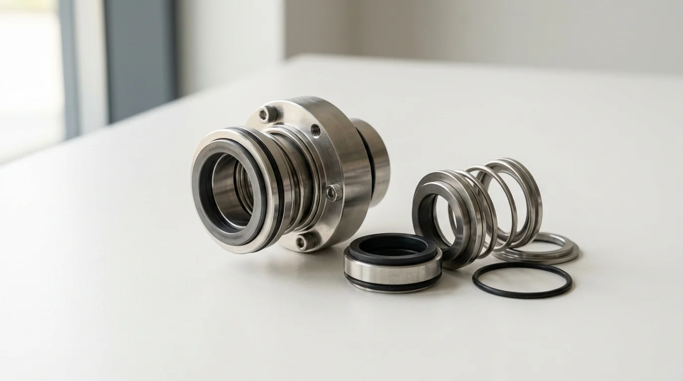
How Mechanical Seals Affect Reliability, Safety, and Cost
In high-pressure pump applications, mechanical seals are the critical interface between process containment and catastrophic failure. As industrial operations push fluid handling systems to higher performance thresholds, the mechanical seal dictates not only the environmental safety of the plant but also the overall lifecycle cost of the pumping equipment. A seal failure in a high-pressure environment can result in hazardous chemical releases, unplanned downtime costing tens of thousands of dollars per hour, and severe damage to the pump shaft and bearings.
Selecting the correct mechanical seal requires moving beyond basic dimensional fitment to understand the thermodynamic and hydrodynamic forces at play. High-pressure applications, typically defined as those operating above 20 bar (290 psi) and often exceeding 100 bar (1,450 psi) in boiler feed or pipeline injection services, demand rigorous engineering. When specified correctly, a highly engineered seal can extend Mean Time Between Failures (MTBF) beyond the API 682 target of 25,000 hours, drastically reducing maintenance overhead and ensuring regulatory compliance.
What mechanical seals do
At their core, mechanical seals prevent pumped fluids from leaking along the rotating shaft and escaping into the atmosphere. They achieve this using two highly polished seal faces—one stationary and one rotating with the shaft—pressed together by mechanical springs or bellows, alongside the hydraulic pressure of the fluid itself. In high-pressure applications, this primary function is complicated by the intense forces acting on the seal components.
The mechanical seal must maintain a microscopic fluid film between these faces, typically ranging from 0.25 to 3.0 microns in thickness. This fluid film provides essential lubrication and cooling. If the pressure forces the faces too close together, boundary lubrication breaks down, leading to dry running, exponential heat generation, and immediate thermal cracking of the seal faces. Conversely, if the pressure causes the faces to deflect and separate, excessive leakage occurs. Therefore, the seal’s primary role in high-pressure regimes is to expertly manage face deformation and maintain this delicate tribological balance.
Key seal terms engineers should know
To navigate high-pressure seal selection, engineers must master several specialized metrics and terms. The most critical is the Pressure-Velocity (PV) limit. The PV value is the product of the pressure drop across the seal faces and the sliding velocity at the mean face diameter. Operating beyond a material’s PV limit guarantees rapid wear and premature failure. For example, standard carbon-graphite faces might have a PV limit of 17.5 MPa-m/s (500,000 psi-ft/min), whereas advanced silicon carbide configurations can handle PV values exceeding 35 MPa-m/s.
Another fundamental concept is the ‘balance ratio,’ which is the ratio of the hydraulic closing area to the seal face area. In high-pressure applications, an unbalanced seal would generate immense friction, destroying the faces. By stepping the shaft or sleeve, engineers create a balanced seal, reducing the balance ratio to a typical range of 0.65 to 0.85. This ensures the closing force is sufficient to prevent leakage but low enough to maintain the lubricating fluid film without generating excessive heat.
Operating Conditions That Define Seal Specifications
Mechanical seals are not off-the-shelf commodities; they are highly application-specific components. The specification process must begin with a comprehensive mapping of the pump’s operating window. High-pressure pumps, such as multistage centrifugal or heavy-duty positive displacement pumps, subject seals to severe dynamic conditions. Failing to account for transient states, such as startup sequences, process upsets, or cleaning cycles, is a leading cause of premature seal mortality.
Engineers must analyze a matrix of variables including thermodynamic limits, fluid rheology, and mechanical dynamics. A specification error in any single parameter can compromise the entire sealing system, leading to volatile organic compound (VOC) emissions or sudden catastrophic depressurization.
Pressure, temperature, speed, and shaft size
The baseline parameters for any seal specification are pressure, temperature, speed, and shaft size. High pressure is not a static condition; seals must withstand maximum allowable working pressure (MAWP), dynamic operating pressure, and transient surge pressures. While standard seals may handle up to 20 bar (290 psi), high-pressure services (e.g., 40 to 150 bar) require robust metal components, optimized O-ring extrusion clearances, and heavy-duty drive mechanisms.
Temperature profiles dictate the selection of secondary sealing elements (elastomers) and influence face distortion. Operating temperatures can range from cryogenic levels (-196°C) in LNG applications to extreme heat (>400°C) in refinery bottom pumps. Speed and shaft size directly determine the sliding velocity at the seal faces. A 100 mm shaft rotating at 3,600 RPM generates significantly more centrifugal force and frictional heat than a 50 mm shaft at the same speed, heavily influencing the required PV capability of the seal face materials.
Fluid properties, solids, and chemical compatibility
The physical and chemical characteristics of the pumped fluid dictate the tribological pairing of the seal faces and the metallurgy of the seal hardware. Viscosity affects the thickness of the lubricating film; highly volatile fluids with low specific gravity and high vapor pressure risk flashing (vaporizing) between the seal faces, causing dry running. To prevent this, the stuffing box pressure must be maintained at a minimum of 0.5 to 1.0 bar above the fluid’s vapor pressure at the operating temperature.
Solids content is a major wear factor. If the fluid contains more than 5% abrasive solids by weight, standard face materials will suffer rapid abrasive wear. Solutions include utilizing hard-on-hard face pairings (like Silicon Carbide vs. Tungsten Carbide) or implementing specific environmental controls to keep particulates away from the seal faces. Furthermore, chemical compatibility is non-negotiable. Corrosive fluids mandate high-alloy metallurgy, such as Hastelloy C-276 or Titanium, and specialized perfluoroelastomers (FFKM) to prevent chemical attack and degradation of the O-rings.
When balanced or specialized seals are needed
The decision between balanced and unbalanced seals is strictly dictated by pressure limits. Unbalanced seals are generally limited to pressures below 10 to 12 bar (145 to 175 psi). In high-pressure applications, balanced seals are mandatory. Specialized designs, such as hydrodynamic gas-lubricated seals or split seals, may also be required depending on accessibility and emission requirements.
| Feature | Unbalanced Mechanical Seals | Balanced Mechanical Seals |
|---|---|---|
| Pressure Limit | Typically < 12 bar (175 psi) | Up to 80+ bar (1,160+ psi) |
| Balance Ratio | > 1.0 (Usually 1.1 to 1.2) | < 1.0 (Usually 0.65 to 0.85) |
| Heat Generation | High (due to high friction) | Low to Moderate (optimized fluid film) |
| Shaft Modification | None required (mounts on straight shaft) | Requires a stepped shaft or sleeve |
| Primary Application | Low-pressure water, mild chemicals | Boiler feed, pipeline, hydrocarbon processing |
For extreme pressures exceeding 100 bar, custom-engineered seals utilizing finite element analysis (FEA) are necessary to predict and counteract mechanical and thermal face deflection. These specialized seals often incorporate multi-stage pressure breakdowns or sophisticated hydrodynamic grooves (such as spiral grooves) to generate lift and maintain face separation under massive compressive loads.
Comparing Mechanical Seal Designs
Selecting the correct mechanical seal architecture and material composition is a critical step in high-pressure pump engineering. The market offers a variety of configurations, from simple single-stage components to complex, multi-barrier cartridge systems. The choice of design impacts not only the initial capital expenditure but also the ease of installation, the footprint of auxiliary support systems, and the long-term reliability of the pump.
In high-pressure environments, the margin for error is virtually zero. Therefore, evaluating seal designs requires a deep understanding of how different face combinations react to friction, and how auxiliary flush plans can artificially alter the micro-environment surrounding the seal to ensure optimal operating conditions.
Single, double, tandem, and cartridge seals
Single seals consist of one set of sealing faces and are suitable for non-hazardous fluids where minor atmospheric leakage is acceptable. However, for high-pressure hazardous applications, dual seals (double or tandem) are required. Tandem seals (unpressurized dual seals) feature a primary seal handling the full product pressure and a secondary seal serving as a backup, capturing any leakage. Double seals (pressurized dual seals) utilize a barrier fluid maintained at a higher pressure than the process fluid, ensuring that if a leak occurs, the barrier fluid enters the pump rather than the process fluid escaping to the atmosphere.
Cartridge seals have become the industry standard for high-pressure applications. Unlike component seals, which require precise measurement and setting of spring compression during installation, cartridge seals are pre-assembled, pre-set, and pressure-tested at the factory. This modular design slides onto the shaft as a single unit, reducing installation errors by an estimated 70% and significantly cutting down maintenance turnaround times.
Seal face materials and compatibility
Seal face material selection defines the wear life and thermal limits of the seal. The standard pairing for general service is Carbon-Graphite against Silicon Carbide (SiC). Carbon provides excellent dry-running properties and self-lubrication, but it has lower pressure limits and can be susceptible to blistering in certain hydrocarbons. For high-pressure and abrasive services, harder materials are required.
| Face Material Combination | Typical PV Limit (MPa-m/s) | Hardness (Vickers HV) | Best Application Profile |
|---|---|---|---|
| Carbon vs. Ceramic | 3.5 | Ceramic: ~1500 | Low pressure, benign chemicals, low cost |
| Carbon vs. Silicon Carbide | 17.5 | SiC: 2500+ | Moderate to high pressure, good lubricity |
| SiC vs. Silicon Carbide | 35.0 | SiC: 2500+ | High pressure, highly abrasive, low lubricity fluids |
| Tungsten Carbide vs. SiC | 45.0 | WC: ~1800 | Extreme pressure, shock loads, abrasive slurries |
Silicon Carbide (SiC) and Tungsten Carbide (WC) are the premium choices for extreme pressures. SiC offers superior thermal conductivity and extreme hardness (Vickers HV 2500+), making it highly resistant to wear and thermal shock. A pairing of SiC against SiC is common for abrasive services, though it requires excellent fluid film lubrication to prevent catastrophic failure from dry running. Tungsten Carbide is tougher and more resistant to mechanical shock, making a WC/SiC pairing ideal for high-pressure pipelines experiencing frequent pressure pulsations.
Flush plans, barrier fluids, cooling, and quench systems
High-pressure seals rarely operate successfully without an auxiliary support system, defined by API 682 piping plans. These systems control the environment around the seal faces by providing cooling, lubrication, or a clean fluid flush. Plan 11 is the most common, routing fluid from the pump discharge through an orifice back to the seal chamber to remove heat. However, in high-pressure services with poor lubricating fluids, more complex plans are necessary.
For dual pressurized seals, a Plan 53 (A, B, or C) system is utilized to supply a clean barrier fluid. The critical metric here is maintaining a positive pressure differential: the barrier fluid must be kept 1.5 to 2.0 bar (20 to 30 psi) above the maximum stuffing box pressure. Plan 53B uses a bladder accumulator for high-pressure barrier fluid storage, while Plan 53C uses a piston accumulator to dynamically track process pressure, ensuring a constant differential even during system pressure spikes. Quench systems (Plan 62) may also be used on the atmospheric side of the seal to introduce steam or nitrogen, preventing the crystallization or coking of any minor process leakage.
Practical Selection and Sourcing Process
Procuring mechanical seals for high-pressure applications is a rigorous engineering exercise, not a standard purchasing transaction. The gap between a seal that technically fits a pump shaft and a seal that operates reliably for years is bridged by accurate data collection and strict adherence to industry standards.
A methodical selection process mitigates risk. By systematically gathering operational data, aligning with global compliance frameworks, and deeply evaluating the technical bandwidth of the seal manufacturer, process engineers can ensure that the selected sealing system will perform under the specific thermodynamic stresses of their facility.
Data to collect before selecting a seal
Before engaging a supplier, engineers must compile a comprehensive data sheet. This goes beyond just “pressure and temperature.” Required data includes the complete pump performance curve to understand operating points versus Best Efficiency Point (BEP). Operating too far from BEP induces shaft deflection and radial loads that can destroy seal faces, regardless of the seal’s pressure rating.
Accurate stuffing box dimensions (bore, depth, distance to first obstruction) are mandatory for cartridge seal fitment. Additionally, engineers must calculate the vapor pressure margin. To prevent fluid vaporization at the seal faces—a primary cause of high-pressure seal failure—the stuffing box pressure must be maintained at least 0.5 to 1.0 bar above the fluid’s vapor pressure at the maximum operating temperature. Gathering fluid safety data sheets (SDS) is also necessary to verify the chemical compatibility of elastomers (like Viton, EPDM, or Kalrez) and metallurgy.
API 682 and other compliance requirements
In the hydrocarbon, petrochemical, and high-pressure processing industries, API Standard 682 (currently in its 4th Edition) is the definitive governing document for mechanical seals. API 682 categorizes seals by shaft size and operating conditions. Category 1 is for moderate temperatures and pressures, while Category 2 and 3 seals are designed for heavier duties. For high-pressure applications (typically exceeding 40 bar or 600 psi), Category 3 seals are generally mandated, featuring larger cross-sections, optimized face geometries, and rigorous qualification testing.
Compliance extends to the seal type and arrangement. API 682 defines Type A (pusher seals with O-rings), Type B (metal bellows), and Type C (high-temperature bellows). Furthermore, environmental regulations driven by agencies like the EPA require strict emissions control. High-pressure pumps handling volatile organic compounds (VOCs) must often demonstrate emissions below 500 parts per million (ppm), a threshold that practically mandates the use of API 682 Arrangement 2 (tandem) or Arrangement 3 (double) dual seal configurations with heavily monitored barrier fluid systems.
How to assess supplier engineering support
The complexity of high-pressure sealing means the supplier must act as an engineering partner rather than a mere vendor. When assessing a seal manufacturer, buyers should evaluate their in-house analytical capabilities. Do they utilize Finite Element Analysis (FEA) to model seal face distortion under 100-bar loads? Do they provide computational fluid dynamics (CFD) modeling for the flush plans to ensure adequate heat removal?
Supply chain logistics and aftermarket support are equally critical. High-pressure, engineered cartridge seals are not typically stocked items; lead times can range from 8 to 12 weeks for standard API seals, and up to 20 weeks for custom metallurgy. Assess the supplier’s global footprint for rapid repair services and their ability to track field MTBF data. A supplier capable of conducting failure root cause analysis (RCA) and providing localized inventory for critical spares will significantly reduce lifecycle costs and unplanned downtime.
Final Decision Framework for Mechanical Seals
The final specification of a mechanical seal for high-pressure pump applications requires synthesizing operational data, material science, and commercial constraints into a cohesive decision. Engineers must navigate the inherent trade-offs between upfront capital expenditure, long-term reliability, and plant safety.
A structured decision framework ensures that the selected seal not only meets the immediate containment requirements but also aligns with the facility’s broader maintenance strategy and regulatory obligations. The goal is to move away from reactive maintenance and achieve predictable, multi-year operational cycles.
Ranking options by reliability, safety, and cost
When ranking seal options, safety and environmental compliance must be the non-negotiable baseline. If the pumped fluid is toxic, highly flammable, or subject to strict VOC emission limits (e.g., < 500 ppm), an unpressurized single seal is disqualified immediately, regardless of cost. In these scenarios, the hierarchy of choice defaults to dual pressurized seals (Arrangement 3) supported by robust Plan 53 barrier systems.
Once safety baselines are met, reliability and cost are weighed. Initial capital cost is often a misleading metric. A custom-engineered, balanced dual cartridge seal with Silicon Carbide faces and a Plan 53B accumulator system may carry a 200% to 300% price premium over a basic single seal. However, in a 60-bar boiler feed application, the single seal may fail every 6 months, whereas the engineered dual seal is designed to hit the API 682 target of 25,000 hours (roughly 3 years) MTBF. When factoring in the cost of pump downtime—often exceeding $10,000 per hour in critical continuous-process plants—the return on investment for the premium seal is realized within the first avoided failure.
Turning specification trade-offs into a final choice
Turning trade-offs into a final choice requires a systematic engineering review checklist. If the application involves high pressure and high shaft speeds, the heat generated will be immense. The trade-off is between specifying a highly complex, externally cooled flush plan (like Plan 23 or Plan 54) versus upgrading the seal face materials to premium grades that tolerate higher PV limits and utilizing a simpler Plan 11 flush.
Ultimately, the final choice should be documented and validated against the pump’s expected operational lifecycle. If the pump operates in a remote pipeline station where maintenance access is difficult, the specification must heavily favor self-contained reliability—such as a robust Plan 53C system that dynamically adjusts barrier pressure without manual intervention. By meticulously balancing face materials, balance ratios, and auxiliary support systems against the hard numerical realities of the application’s pressure, temperature, and MTBF targets, engineers can finalize a specification that guarantees high-pressure containment and operational excellence.
Key Takeaways
- Treat pump services above 20 bar (290 psi) as high-pressure applications that require engineered seal selection rather than simple dimensional matching.
- Check the seal’s PV limit against the actual pressure drop and shaft speed to prevent rapid face wear and heat-related failure.
- Use balanced seal designs in high-pressure pumps to reduce face loading, with typical balance ratios ranging from 0.65 to 0.85.
- Maintain the microscopic 0.25 to 3.0 micron fluid film between seal faces by selecting compatible materials, geometry, and operating conditions.
- Choose advanced face materials such as silicon carbide when standard carbon-graphite cannot meet the application’s pressure-velocity demands.
- Specify seals with lifecycle reliability in mind, because correct selection can help extend MTBF toward or beyond the API 682 target of 25,000 hours.
Frequently Asked Questions
What pressure range is considered high pressure for pump mechanical seals?
High-pressure pump service is typically considered above 20 bar (290 psi), with demanding applications such as boiler feed or pipeline injection often exceeding 100 bar (1,450 psi).
Why is seal balance important in high-pressure applications?
A balanced mechanical seal reduces hydraulic closing force on the seal faces, limiting friction, heat, and wear. For high-pressure service, balance ratios commonly fall between 0.65 and 0.85.
What does PV limit mean when selecting a mechanical seal?
PV limit is the product of pressure drop and sliding velocity at the seal face. Exceeding a material’s PV limit causes rapid wear, overheating, and premature seal failure.
Which seal face materials are suitable for high-pressure pumps?
Material choice depends on pressure, speed, fluid, and temperature. Standard carbon-graphite may suit moderate PV values, while silicon carbide configurations can handle much higher PV limits.
How thin is the lubricating film between mechanical seal faces?
The fluid film between seal faces is typically only 0.25 to 3.0 microns thick. Maintaining this film is essential for lubrication, cooling, and leakage control.

Post time: Aug-05-2026