


Why Cartridge Mechanical Seals Matter for Pump Maintenance
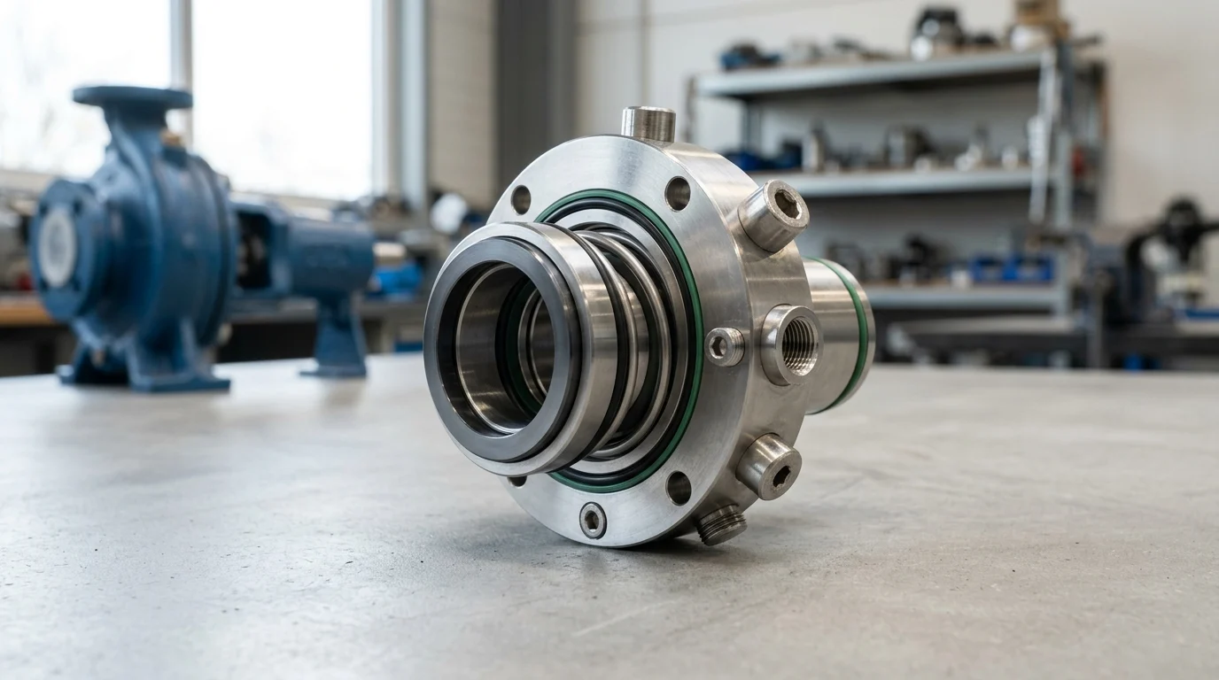
The transition from component to cartridge mechanical seals represents a critical evolution in industrial pump maintenance. By integrating the seal faces, secondary elastomers, sleeve, and gland into a single, pre-assembled unit, cartridge seals eliminate the complex, error-prone installation procedures associated with traditional component seals. Industry data routinely indicates that mechanical seal failures account for up to 70% of unplanned pump downtime, with installation and handling errors driving a significant portion of these failures.
Adopting cartridge seals mitigates these operational risks by removing the need for manual spring compression measurements and delicate face handling during assembly on the plant floor. This shift not only extends the operational lifespan of rotating equipment but also standardizes maintenance workflows across diverse fluid-handling applications.
How cartridge seals reduce installation variability
Component seals require technicians to measure and mark the shaft, carefully calculate the working length, and manually set the seal to achieve the correct spring compression. This process is highly sensitive to human error; a deviation of just 1.5 mm (0.060 inches) can lead to either excessive face pressure—causing premature wear and thermal degradation—or insufficient compression, resulting in immediate leakage upon startup.
Cartridge seals reduce this installation variability by utilizing removable setting clips that hold the seal faces at the exact engineered compression during installation. Once the seal is bolted to the pump casing and the set screws are secured to the shaft, technicians simply disengage or remove these clips. This engineered precision guarantees that the internal spring loading remains exactly as specified by the manufacturer, effectively reducing installation time from over an hour to less than twenty minutes. Furthermore, this self-contained architecture protects the precision-lapped seal faces from contamination by ambient dust, dirt, and oils from technicians’ hands during the fitting process.
What to define before selection
Before selecting a cartridge mechanical seal, engineers must clearly define the operating envelope of the pump. Primary parameters include the fluid’s chemical composition, specific gravity, viscosity, operating temperature, and the dynamic pressure within the seal chamber (stuffing box). Accurately determining the seal chamber pressure is critical, as it often differs significantly from the pump’s overall discharge pressure.
For standard single-stage centrifugal pumps, the stuffing box pressure is typically calculated as the suction pressure plus 10% to 25% of the differential pressure, depending on the specific impeller design and the presence of balancing holes. Engineers must also evaluate the pump’s rotational speed, which dictates the peripheral velocity at the seal faces. Exceeding the pressure-velocity (PV) limit of the chosen face materials will lead to rapid vaporization of the fluid film and subsequent dry-running destruction. Defining these baseline parameters ensures the selected cartridge seal operates safely within its designed mechanical and thermal thresholds.
How to Match Cartridge Seals to Pump Duty and Fluid

Matching a cartridge mechanical seal to specific duty and fluid conditions requires a comprehensive understanding of the process fluid’s tribological behavior. The pumped fluid must provide adequate lubrication and cooling to the seal faces; otherwise, the resulting friction will cause catastrophic thermal failure. Applications involving highly viscous fluids, volatile organic compounds (VOCs), or heavy particulate loads demand specialized seal configurations and robust material selections to maintain a stable, continuous fluid film between the rotating and stationary faces.
When to use single, double, or tandem seals
The choice between single, double (pressurized dual), and tandem (unpressurized dual) cartridge seals hinges on fluid hazards, regulatory compliance, and inherent fluid lubricity. Single cartridge seals are the industry standard for non-hazardous, lubricating fluids like water or light oils, typically operating successfully up to 20 bar (290 PSI) depending on the specific seal design and balance ratio.
When handling toxic, carcinogenic, or highly volatile fluids, environmental regulations frequently mandate zero-emission sealing solutions to maintain local VOC emissions below 500 ppm. Double cartridge seals utilize a pressurized barrier fluid maintained at 1.5 to 2.0 bar (20 to 30 PSI) above the stuffing box pressure. This pressure differential ensures that any microscopic leakage across the inner seal faces consists of clean barrier fluid entering the process, rather than hazardous process fluid escaping to the atmosphere. Tandem seals employ an unpressurized buffer fluid and are primarily used to prevent crystallization of the process fluid upon atmospheric contact, or to provide secondary safety containment in high-pressure hydrocarbon applications.
How to choose materials, face pairs, elastomers, and springs
Material selection for seal faces, elastomers, and metallurgy dictates the seal’s chemical compatibility and thermal resilience. For seal faces, Carbon versus Silicon Carbide (SiC) is a common pairing for general water and light chemical duties, offering excellent self-lubricating properties. For abrasive applications, a hard-on-hard combination like SiC versus SiC or Tungsten Carbide (TC) is required to prevent abrasive scoring.
Elastomer selection is equally critical: standard Nitrile (NBR) is limited to 90°C (194°F), while Fluoroelastomers (FKM/Viton) extend the thermal limit to 204°C (400°F). For extreme chemical aggression, Perfluoroelastomers (FFKM/Kalrez) are deployed, capable of withstanding temperatures up to 327°C (620°F). Metallic components must also resist corrosion; while 316 Stainless Steel is standard, high-chloride environments necessitate upgrades to Hastelloy C-276 or Alloy 20 to prevent chloride stress corrosion cracking, which can cause spring failure within weeks of operation.
| Face Material Pairing | Typical Max Temperature | Relative Abrasion Resistance | Primary Application Profile |
|---|---|---|---|
| Carbon vs. Ceramic | 150°C (300°F) | Low | Clean water, light chemicals, low-cost duties |
| Carbon vs. Silicon Carbide (SiC) | 200°C (392°F) | Moderate | General industrial, boiler feed, low-viscosity oils |
| SiC vs. Silicon Carbide (SiC) | 400°C (752°F) | High | Abrasive slurries, high-pressure processing |
| Tungsten Carbide vs. Tungsten Carbide | 400°C (752°F) | Very High | Severe abrasion, high-impact environments |
Where split and slurry cartridge seals fit
Split cartridge seals and slurry cartridge seals serve highly specialized roles where standard configurations prove mechanically or economically inadequate. Split seals are engineered for large-scale equipment, such as double-suction split-case pumps or massive cooling water pumps featuring shaft diameters exceeding 63.5 mm (2.5 inches). The highly engineered split design allows technicians to install the seal without decoupling the motor or dismantling the heavy pump casing, effectively reducing a multi-day maintenance task to a few hours.
Conversely, slurry cartridge seals are designed to handle fluids containing high concentrations of suspended solids, often exceeding 10% by weight. Standard internal springs can easily clog and pack out with particulate matter in these environments. Slurry seals overcome this by utilizing large, stationary coil springs or robust bellows located entirely outside the fluid path. Additionally, slurry seals feature heavy-duty face geometries designed to withstand the aggressive scouring action of mining tailings, paper stock, or dense wastewater sludge.
How to Compare Cartridge Mechanical Seal Specifications
Transitioning from conceptual design to formal procurement requires rigorous evaluation of cartridge mechanical seal specifications. Engineers must analyze mechanical tolerances, dimensional standards, and long-term economic factors to ensure the selected seal meets both operational requirements and budget constraints. A poorly specified seal, even if mechanically sound, can lead to excessive auxiliary system costs or compliance failures.
How to compare single versus double cartridge seals
Comparing single and double cartridge seals at the specification level involves analyzing pressure differentials, thermal limits, and auxiliary system requirements. A single cartridge seal specification must detail the maximum allowable stuffing box pressure, the balance ratio, and the necessary flush arrangements to dissipate frictional heat. It remains a fundamentally simpler specification focused directly on the interaction between the seal and the process fluid.
In contrast, a double cartridge seal specification is inherently more complex, requiring precise calculation of the barrier fluid pressure dynamics. The specification must explicitly dictate that the barrier fluid pressure remains consistently 1.5 to 2.0 bar higher than the maximum dynamic stuffing box pressure under all operating conditions. Furthermore, the double seal specification must detail the internal pumping ring design—whether axial or radial—used to circulate the barrier fluid through the external cooling loop. Pumping ring efficiency directly impacts the thermal dissipation capacity, which is critical since a double seal generates frictional heat from two distinct sets of seal faces rather than one.
Which API, ISO, ANSI, and industry standards apply
Industrial standards govern the design, testing, and application of mechanical seals to ensure safety, reliability, and interchangeability across global facilities. The American Petroleum Institute (API) Standard 682 (4th Edition) is the definitive standard for the oil, gas, and petrochemical sectors. It categorizes seals based on shaft size, temperature, and pressure. For instance, Category 1 seals are designed for non-API 610 pumps operating at temperatures up to 260°C (500°F) and pressures up to 22 bar (315 PSI), while Category 2 and 3 seals are mandated for API 610 heavy-duty process pumps under more severe conditions.
In chemical processing and general manufacturing, ANSI/ASME B73.1 and B73.2 standards dictate the dimensional envelope of the seal chamber, ensuring that any ANSI-compliant cartridge seal will physically fit into any ANSI-compliant pump without casing modifications. Similarly, ISO 21049 and ISO 3069 establish international dimensional requirements for seal cavities, facilitating global standardization for multinational operators.
What lifecycle cost drivers to evaluate
Evaluating lifecycle cost drivers requires moving beyond the initial purchase price to calculate the Total Cost of Ownership (TCO). The initial capital expenditure (CAPEX) of a cartridge seal typically represents only 15% to 20% of its comprehensive lifetime cost. The primary economic driver is the Mean Time Between Failures (MTBF). Upgrading from a basic component seal to a properly specified, application-specific cartridge seal can extend MTBF from an average of 12 months to over 36 months.
Engineers must evaluate the cost of process fluid leakage, the energy consumption associated with seal face friction, and the ongoing expense of barrier fluid maintenance. Additionally, the repairability of the cartridge seal is a significant cost driver; high-quality cartridge seals are designed to be refurbished at specialized repair centers for approximately 40% to 50% of the cost of a completely new unit. Factoring in these refurbishment cycles significantly reduces long-term operational expenditures (OPEX) and improves the return on investment.
Practical Selection and Installation Process
The practical selection and installation process dictates the ultimate success or failure of the cartridge mechanical seal. Even the most meticulously engineered, high-specification seal will fail prematurely if installed in a pump with degraded mechanical conditions or if operated without the correct auxiliary support systems. A disciplined approach to mechanical verification and commissioning is mandatory.
How to verify shaft size and seal chamber dimensions
Before unboxing the cartridge seal, maintenance personnel must rigorously verify the mechanical integrity of the pump’s rotating assembly. The shaft or sleeve diameter must be measured using precision micrometers to ensure it falls within the standard tolerance of +0.00 mm to -0.05 mm (+0.000 to -0.002 inches) of the nominal size. Undersized or fretted shafts will fail to properly engage the internal dynamic O-ring, causing immediate atmospheric leakage.
Furthermore, technicians must use dial indicators to measure shaft radial runout, which must not exceed 0.05 mm (0.002 inches) Total Indicator Reading (TIR). Excessive runout forces the seal faces to absorb severe lateral movement, leading to rapid wear and elastomer degradation. Axial end play must also be restricted to a maximum of 0.08 mm (0.003 inches) to prevent the seal’s springs from bottoming out or losing essential compression. Finally, the seal chamber bore and depth must be verified to ensure adequate clearance for the cartridge gland and internal rotating components, allowing for proper fluid circulation around the seal faces.
How to choose the correct seal support plan and barrier fluid
Cartridge seals rely heavily on external support systems, standardized as API Piping Plans, to maintain an optimal operating environment. The selection of the piping plan and the associated buffer or barrier fluid is critical to preventing thermal degradation and ensuring long-term reliability.
| API Piping Plan | Configuration | Fluid Type | Application Rationale |
|---|---|---|---|
| Plan 11 | Discharge bypass to seal | Process fluid | Standard flush for single seals; removes heat and vents air |
| Plan 52 | Unpressurized reservoir | Buffer fluid | Tandem seals; captures inner seal leakage, prevents crystallization |
| Plan 53A | Pressurized reservoir (gas) | Barrier fluid | Double seals; maintains 1.5–2.0 bar positive pressure over stuffing box |
| Plan 54 | External pressurized system | Barrier fluid | High-heat double seals; provides independent, high-flow cooling |
For single seals, an API Plan 11 is the most common arrangement, routing fluid from the pump discharge through a flow-restricting orifice to flush the seal faces, providing cooling and sweeping away particulates. For double seals, an API Plan 53A is frequently utilized, employing a pressurized reservoir of barrier fluid. The barrier fluid itself must possess excellent lubricity, high specific heat capacity, and absolute chemical compatibility with the process fluid. Common choices include synthetic PAO oils for hydrocarbon services, or water/glycol mixtures for lower-temperature chemical applications.
What commissioning steps prevent dry running
Commissioning is the most vulnerable phase in a mechanical seal’s lifecycle. Dry running, even for a few seconds, can cause the face temperatures to spike by over 300°C (572°F), leading to thermal cracking, blistering, and catastrophic structural failure of the seal faces.
To prevent this, the seal chamber must be thoroughly vented to eliminate trapped air pockets before the pump motor is energized. For double seals, the barrier fluid system must be filled, vented, and fully pressurized to the specified 1.5 to 2.0 bar differential before the process fluid is introduced into the pump casing. Technicians should manually rotate the pump shaft by hand to ensure free movement and to help distribute the initial lubricating fluid film across the lapped seal faces. Finally, operators should monitor the seal gland for excessive heat generation or abnormal acoustic emissions during the initial startup sequence, which serve as early indicators of inadequate lubrication.
How to Make the Final Seal Selection
Making the final seal selection involves synthesizing mechanical specifications, fluid dynamics, and installation requirements into a cohesive procurement strategy. This final phase requires evaluating supplier capabilities, standardizing inventory, and applying a rigid decision framework that optimizes plant-wide maintenance protocols and budget utilization.
When to standardize cartridge seals across pumps
Standardizing cartridge seals across a facility yields substantial economic and operational benefits. By analyzing the plant’s rotating equipment roster, engineers can often identify a modular cartridge seal design capable of servicing up to 80% of the centrifugal pumps on site. Standardization dramatically reduces inventory carrying costs by minimizing the number of unique stock keeping units (SKUs) required in the warehouse.
Furthermore, it streamlines maintenance training; when technicians work with a standardized seal geometry and consistent installation procedure, the probability of fitting errors decreases exponentially. Standardization should be implemented by grouping pumps into categories based on shaft diameter, ANSI/API dimensional standards, and broad fluid compatibility classifications. This approach allows a single high-specification seal (e.g., utilizing an FFKM elastomer and SiC/SiC faces) to cover multiple less-demanding applications economically through economies of scale.
How to evaluate suppliers and technical support
The technical complexity of mechanical seals necessitates a strong, ongoing partnership with the manufacturer. Evaluating suppliers requires looking beyond the initial purchase price to assess their engineering depth and post-sale support capabilities. A premier supplier must offer localized repair facilities equipped to perform detailed failure analysis, precision re-lapping of seal faces, and certified pressure testing.
The supplier should mandate a static air test at 1.7 bar (25 PSI) for all newly assembled or repaired cartridge seals before dispatch to guarantee zero leakage out of the box. Additionally, engineers should evaluate the supplier’s material traceability protocols. It is essential that all wetted metallurgical components can be supplied with EN 10204 3.1 material test certificates, which are critical for maintaining compliance in the petrochemical, pharmaceutical, and food processing industries.
What final decision framework to use
The final decision framework must balance capital expenditure against long-term reliability using a robust Total Cost of Ownership (TCO) model. The evaluation matrix should weight technical compliance (e.g., meeting API 682 Category 1 specifications or specific thermal thresholds) as a non-negotiable baseline.
From that baseline, the framework should score competing options based on the projected Mean Time Between Failures (MTBF), the energy efficiency of the specific seal face design, and the availability of local repair infrastructure. Engineers must also factor in the cost of necessary auxiliary systems, such as API Plan 53A reservoirs and instrumentation, when evaluating double cartridge seals. By meticulously applying this framework, maintenance and reliability teams can select cartridge mechanical seals that not only ensure environmental compliance and operational safety but also deliver a quantifiable reduction in lifecycle pumping costs.
Key Takeaways
- Choose cartridge mechanical seals to reduce installation errors because the faces, sleeve, gland, and elastomers are supplied as a pre-assembled unit.
- Verify seal chamber pressure instead of relying only on pump discharge pressure, since stuffing box pressure can differ significantly from overall discharge pressure.
- Use the pump fluid’s chemistry, viscosity, specific gravity, temperature, and lubricity to select compatible face materials and elastomers.
- Avoid incorrect spring loading because even a 1.5 mm setting error can cause premature wear, overheating, or immediate leakage.
- Check pressure-velocity limits for the selected face materials to prevent fluid film collapse and dry-running damage.
- Consider double cartridge seals for hazardous, abrasive, crystallizing, or poor-lubricating fluids where additional containment and face protection are required.
Frequently Asked Questions
Why are cartridge mechanical seals easier to maintain than component seals?
Cartridge seals are pre-assembled with the seal faces, sleeve, elastomers, and gland in one unit. This removes many manual setup steps, reduces handling damage, and helps technicians install the seal with the correct spring compression.
What pump data should be checked before selecting a cartridge seal?
Confirm the fluid chemistry, viscosity, specific gravity, temperature, seal chamber pressure, shaft speed, and pump design. These factors determine seal face materials, elastomers, balance type, and whether a single or double cartridge seal is appropriate.
How does seal chamber pressure affect cartridge seal selection?
Seal chamber pressure defines the load on the seal faces and influences heat generation, leakage risk, and face material choice. It may differ from discharge pressure, so engineers should calculate or measure it accurately before selection.
When should a double cartridge mechanical seal be used?
A double cartridge seal is often preferred for hazardous, toxic, abrasive, crystallizing, or poor-lubricating fluids. It can use a barrier or buffer fluid to protect seal faces, improve reliability, and reduce emissions.
Can cartridge seals reduce pump downtime?
Yes. Mechanical seal failures can cause a large share of unplanned pump downtime, and installation errors are a common contributor. Cartridge designs reduce setup variability and can shorten installation from over an hour to less than twenty minutes.

Post time: Aug-08-2026