


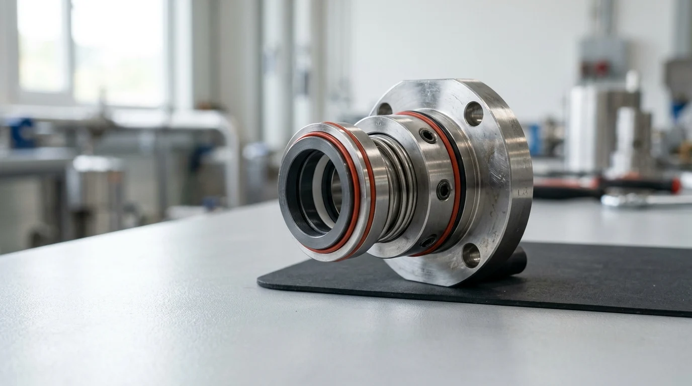
Why Abnormal Wear in Chemical Pump Mechanical Seals Matters
Mechanical seals serve as the primary containment barrier in centrifugal chemical pumps, preventing hazardous, corrosive, and high-value process fluids from escaping into the atmosphere. Because they rely on microscopic fluid films and highly precise tolerances, these components are inherently sensitive to operational and mechanical deviations. Within the chemical processing industry, historical reliability data indicates that mechanical seal failures account for approximately 60% to 70% of total pump maintenance expenditures.
Understanding and diagnosing abnormal wear in these seals is not merely a maintenance exercise; it is a critical requirement for facility safety, regulatory compliance, and operational profitability. When a seal degrades prematurely, it signals an underlying systemic issue that, if left unaddressed, will continue to consume replacement parts and labor while exposing the plant to severe operational risks. Effective diagnosis transforms unpredictable breakdowns into manageable, data-driven reliability improvements.
Leakage, emissions, downtime, and spare parts impact
The consequences of abnormal mechanical seal wear extend far beyond the direct cost of a replacement cartridge. Leakage of volatile, toxic, or flammable chemicals presents immediate occupational hazards and severe environmental compliance risks. For example, under the United States Environmental Protection Agency (EPA) Method 21 regulations, fugitive emissions exceeding 500 parts per million (ppm) of volatile organic compounds (VOCs) trigger mandatory, time-sensitive repair protocols and potential regulatory fines.
Furthermore, the economic impact of process downtime often dwarfs the hardware costs. In continuous chemical processing units, an unscheduled pump shutdown due to a catastrophic seal failure can incur production losses ranging from $10,000 to over $50,000 per hour. Additionally, plants suffering from chronic, undiagnosed seal wear are forced to maintain artificially high inventories of expensive engineered spare parts, tying up capital in warehouse stock to mitigate the risk of prolonged outages.
Normal wear vs abnormal wear vs progressive failure
Distinguishing between normal, expected wear and abnormal degradation is the foundational step in mechanical seal diagnostics. Normal wear involves the gradual, uniform microscopic degradation of the sacrificial seal face, typically the softer carbon component in a carbon-versus-silicon-carbide tribological pair. Under ideal conditions, API 682 standards project a minimum continuous operating life of 24,000 hours (roughly three years) for a mechanical seal, during which the face wear remains steady and predictable.
Abnormal wear, conversely, is characterized by rapid, asymmetrical, or destructive degradation that forces the seal out of service long before its 24,000-hour design life—often within the first 1,000 hours of operation. This type of wear is symptomatic of boundary condition violations, such as loss of lubrication or excessive mechanical deflection. If abnormal wear is not intercepted, it leads to progressive failure. Progressive failure occurs when the initial damage, such as thermal distortion of the seal face, causes localized flashing of the process fluid, which in turn leads to rapid temperature escalation, subsequent elastomer carbonization, and ultimately, a catastrophic loss of containment.
Visible Wear Patterns That Indicate Seal Problems
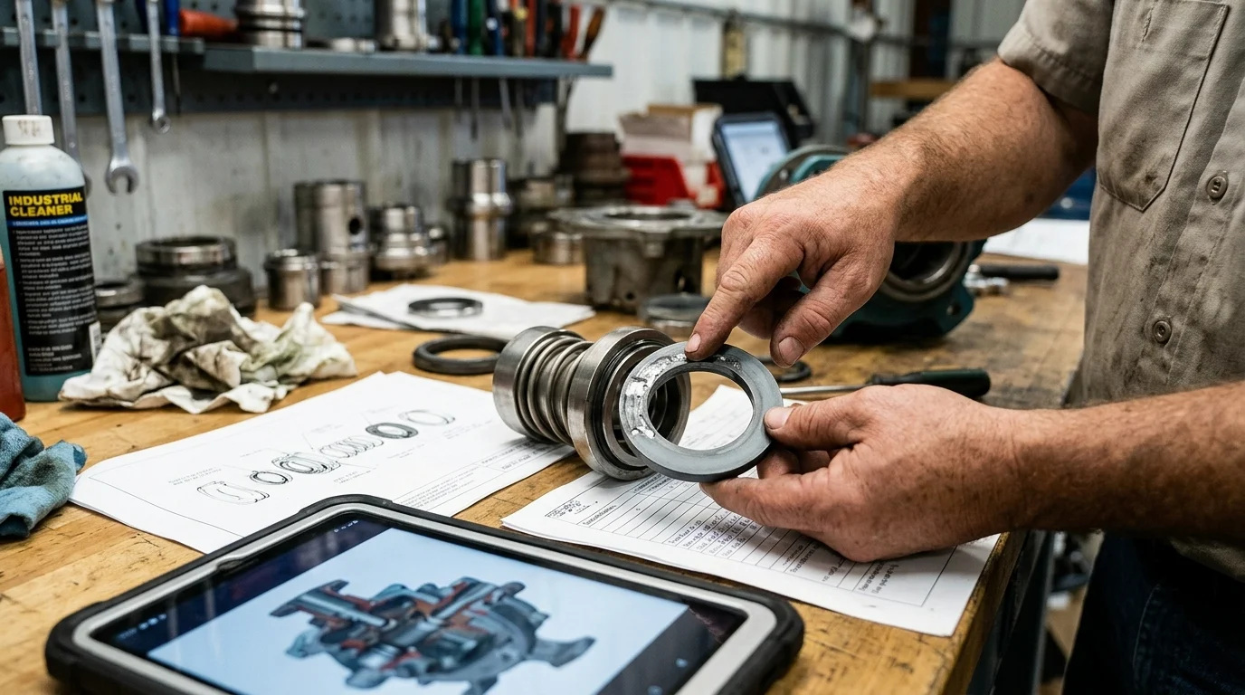
Visual inspection of a failed mechanical seal during a teardown provides the most direct empirical evidence of the failure mode. Because the clearance between operating seal faces is incredibly small—typically between 0.25 and 1.0 microns—even microscopic disruptions to the surface topography can induce massive leakage. Analyzing the physical condition of the extracted components allows reliability engineers to trace the damage back to its specific mechanical, thermal, or chemical origin.
To accurately assess seal face flatness, maintenance technicians utilize an optical flat combined with a monochromatic light source. In a healthy or normally worn seal, the surface distortion will not exceed 2 to 3 helium light bands, which equates to approximately 0.58 to 0.87 microns of deviation. When wear becomes abnormal, visible physical deformities emerge across the seal’s critical components, far exceeding these microscopic tolerances.
Seal face, spring, sleeve, elastomer, and gland wear signs
Each component of a mechanical seal reacts differently to adverse operating conditions. The primary seal faces may exhibit deep concentric grooving, which strongly suggests abrasive particulate entrapment. Alternatively, hard faces made of silicon carbide or tungsten carbide may display heat checking—a series of fine, radial cracks radiating from the center of the seal ring out to the edge, indicative of rapid thermal cycling and localized fluid vaporization. On carbon faces, engineers might observe blistering, where subsurface porosity expands and fractures the mating surface due to rapid pressure drops or high-viscosity fluid shearing.
Beyond the seal faces, secondary components offer vital clues. Coil springs or stationary bellows can become clogged with crystallized product or process sludge, preventing the faces from tracking each other dynamically. The shaft sleeve may exhibit severe fretting wear, characterized by a distinct groove worn into the metal where the dynamic O-ring constantly micro-cycles. Elastomers themselves are highly expressive of process upsets; O-rings may appear extruded with a “nibbled” edge, signaling over-pressurization, or they may become hard and brittle, pointing to temperature limits being severely exceeded.
Wear appearance and likely root cause comparison
Correlating the visual appearance of a damaged seal component with its most probable root cause is the cornerstone of effective failure analysis. A structured comparison prevents maintenance teams from merely treating the symptom (the leak) and forces them to address the underlying process or mechanical deviation.
| Wear Pattern / Appearance | Affected Component | Likely Root Cause | Quantitative Indicator / Threshold |
|---|---|---|---|
| Heat Checking (Radial Cracks) | Hard Face (SiC / Tungsten Carbide) | Dry running or fluid vaporization | Localized face temperatures exceeding 200°C |
| Deep Concentric Grooving | Soft Face (Carbon / Resin-bonded) | Abrasive solids suspended in fluid | Particle sizes > 10 microns without proper flush |
| Extrusion or “Nibbling” | Elastomer O-rings | Excessive pressure or chemical swelling | Volume swell > 15% or pressure > 40 bar |
| Fretting Wear Groove | Shaft Sleeve under dynamic O-ring | Micro-movement from shaft deflection | Sleeve diameter reduction > 0.05 mm |
| Blistering / Pitting | Carbon Primary Ring | High fluid viscosity or rapid depressurization | Viscosity > 3,000 cSt causing sub-surface shear |
By utilizing this comparative framework, reliability teams can quickly categorize the failure. For instance, discovering a shattered silicon carbide face alongside a melted O-ring immediately directs the investigation toward a catastrophic loss of suction pressure or a dead-headed pump scenario, rather than a slow chemical attack.
Common Causes of Abnormal Mechanical Seal Wear
The root causes of abnormal mechanical seal wear generally fall into three distinct categories: operational parameters, chemical fluid properties, and mechanical equipment conditions. A mechanical seal is not an independent machine; it is a highly sensitive instrument that reflects the overall health of the pump and the stability of the hydraulic system.
Identifying the correct root cause requires a holistic view of the pump’s operating environment. Even the most robust, highly engineered seal will fail prematurely if the boundary conditions it was designed to withstand are routinely violated. Understanding how specific stressors physically destroy seal components is essential for implementing permanent corrective actions.
Dry running, vapor pressure margin, cavitation, and heat
Mechanical seals rely on a microscopic film of the pumped fluid to provide lubrication and cooling between the rotating and stationary faces. When this fluid film vaporizes or is absent, the seal experiences dry running. The immediate result is a drastic spike in the coefficient of friction, leading to extreme heat generation. This localized heat causes thermal distortion of the seal faces, breaking the flat sealing plane and allowing further leakage.
Vaporization often occurs when the vapor pressure margin is too narrow. The fluid temperature in the stuffing box must remain safely below its boiling point at the given box pressure. Additionally, cavitation within the pump—caused when the Net Positive Suction Head Available (NPSHa) fails to exceed the Net Positive Suction Head Required (NPSHr) by a minimum margin of 1.0 to 1.5 meters—sends severe hydraulic shockwaves through the fluid. These shockwaves collapse vapor bubbles violently against the seal faces, causing micro-pitting and forcefully separating the faces, which destroys the lubricating film.
Chemical compatibility, solids, crystallization, and corrosion
Chemical processing applications frequently subject seals to aggressive media that attack the materials of construction. Chemical incompatibility is most often observed in the secondary sealing elements (elastomers). If an O-ring material, such as FKM or EPDM, is mismatched with the process solvent, it will absorb the fluid and swell. An O-ring volume swell greater than 15% will lock the dynamic seal components in place, preventing the springs from keeping the faces closed and leading to immediate, heavy leakage.
Furthermore, fluids containing high concentrations of suspended solids or slurries act as a grinding paste. If abrasive particles larger than 10 microns penetrate the fluid film, they will physically machine away the carbon faces. Similarly, certain chemicals, like sodium hydroxide (caustic soda), have a high tendency to crystallize when exposed to atmospheric air on the low-pressure side of the seal. These hard crystals build up under the seal faces and springs, forcing the faces apart. Corrosion, whether uniform chemical attack or localized pitting on the metallurgy of the seal cartridge, also compromises the structural integrity of the springs and drive pins.
Installation error, shaft alignment, piping strain, and vibration
Even if hydraulic and chemical conditions are perfect, mechanical anomalies will rapidly destroy a seal. Installation errors, such as failing to set the correct seal working length or striking the brittle silicon carbide faces during assembly, account for a significant percentage of premature failures. Mechanical seals require absolute precision; they cannot compensate for grossly misaligned equipment.
Shaft alignment and rigidity are paramount. If the pump shaft exhibits radial deflection exceeding 0.05 mm (0.002 inches) at the seal faces, the dynamic component must constantly adjust to maintain contact, leading to fretting wear and elastomer fatigue. This deflection is often exacerbated by piping strain, where improperly supported heavy pipes physically distort the pump casing. Finally, excessive vibration—defined by ISO 10816-7 as continuous operation exceeding 3.0 mm/s Root Mean Square (RMS) velocity—will shake the seal faces apart, causing chipping, spring failure, and the immediate ingress of destructive particles into the sealing gap.
Diagnostic Process for Maintenance and Reliability Teams
Transitioning from recognizing abnormal wear to definitively proving its root cause requires a systematic diagnostic methodology. Maintenance and reliability teams must avoid the temptation to simply replace the failed seal, wash the pump, and return it to service without investigation. A “replace and restart” mentality guarantees that the exact same failure will occur again, compounding maintenance costs and downtime.
Industry data demonstrates that standardizing on a rigorous, multi-step root cause analysis (RCA) protocol for mechanical seal failures reduces repeat failure rates by an average of 40%. This process involves gathering empirical data while the pump is still in the field, analyzing operational history, and conducting a controlled, forensic teardown of the damaged components.
Evidence to collect before shutdown
The diagnostic process must begin before the pump is isolated and locked out for repair. Critical evidence is highly volatile and disappears once the equipment is shut down. Reliability engineers must capture real-time operational metrics, including suction pressure, discharge pressure, fluid temperature, and localized vibration spectra. If the pump utilizes an external seal support system, such as an API 682 flush plan, its parameters must be recorded immediately.
For example, if the pump utilizes an API Plan 53 barrier fluid system for a dual seal arrangement, the barrier fluid pressure must be verified. Specifications dictate that the barrier pressure must be maintained at 1.5 to 2.0 bar (22 to 30 psi) above the maximum stuffing box pressure. If the gauge reads below this threshold before shutdown, the team immediately knows that process fluid has likely breached the inner seal, reversing the intended pressure differential and causing the wear.
Separating seal design limits from operating problems
Once field data is secured, the next step is to compare the actual operating conditions against the mechanical seal’s original design limits. Every mechanical seal is engineered for a specific operating envelope, detailed on its API data sheet or manufacturer specification document. The team must look for discrepancies between the designed fluid viscosity, specific gravity, temperature limits, and shaft speed versus what the pump is actually experiencing in the current process.
It is crucial to differentiate between a temporary system upset—such as a brief dead-heading event caused by a closed discharge valve—and a continuous boundary condition violation, such as a permanent change in the process fluid temperature or a steady decline in available NPSH due to a clogged suction strainer. Analyzing distributed control system (DCS) historical trends over the 48 hours preceding the failure often reveals pressure spikes or temperature excursions that perfectly align with the physical damage observed later.
Key measurements, tests, and photographs
The final phase of the diagnostic process is the physical teardown, which should be conducted in a clean environment, not on a dirty shop floor. As the seal is disassembled, technicians must take high-resolution macro photographs of every component before cleaning them, as the location of sludge, crystallization, or heat discoloration provides vital context.
Key measurements must be taken to quantify the mechanical state of the pump and the seal. Technicians should use a dial indicator to measure shaft runout and concentricity, ensuring they fall within the strict < 0.05 mm tolerance. The seal faces should be cleaned and tested on an optical flat under monochromatic light to count the helium light bands, objectively measuring the degree of thermal or mechanical distortion. Finally, micrometers should be used to measure the shaft sleeve diameter to check for fretting wear, and calipers to measure the cross-section of the O-rings to calculate the exact percentage of chemical volume swell.
Repair, Redesign, or Upgrade Decisions
The ultimate objective of diagnosing abnormal mechanical seal wear is to implement permanent, engineered corrective actions. Once the root cause is isolated, reliability engineers face a critical decision: repair the seal in-kind, redesign the seal support system, or upgrade the mechanical seal technology entirely. Replacing a seal with the exact same model is only appropriate if the failure was caused by an isolated, non-recurring event, such as a one-time dry running incident due to operator error.
However, if the diagnostic process reveals continuous boundary condition violations or inherent chemical incompatibilities, an upgrade is mandatory. Capital investments in advanced seal technologies or environmental controls are easily justified when evaluated against the staggering costs of chemical leakage, lost production, and chronic maintenance interventions.
When to change face materials, flush plans, or seal design
Changing face materials is the most common and cost-effective redesign. If diagnostics reveal deep grooving from abrasives, moving from a Carbon-versus-Silicon-Carbide arrangement to a hard-on-hard pairing, such as Silicon-Carbide-versus-Silicon-Carbide (SiC/SiC), drastically increases abrasion resistance. If chemical swelling is observed, upgrading elastomers from standard FKM to perfluoroelastomers (FFKM) provides near-universal chemical resistance, despite a higher initial cost.
Upgrading the API flush plan is often required to alter the seal’s operating environment. If a seal is failing from heat checking due to poor lubrication, upgrading from a simple API Plan 11 (recirculation from pump discharge) to an API Plan 32 (injection of a clean, cool external flush fluid) can fundamentally solve the problem. In cases of severe toxicity or where crystallization cannot be managed by a single seal, redesigning the pump to accept a dual pressurized seal cartridge (API Plan 53A or 54) ensures absolute zero-emissions containment.
Lifecycle cost, safety compliance, and lead time factors
Decisions regarding seal upgrades must be driven by Lifecycle Cost (LCC) analysis rather than initial purchase price. Upgrading from a single seal to a dual pressurized seal system may require a capital expense of $5,000 to $15,000, including the support reservoir and instrumentation. However, if this upgrade increases the Mean Time Between Failures (MTBF) from 12 months to over 48 months, the return on investment is realized within the first year of avoided downtime.
Safety compliance also dictates upgrade paths. Facilities operating under stringent regional environmental mandates may be legally required to upgrade to dual seals if single seals repeatedly fail emission audits. Finally, lead time factors must be considered during the decision process. Highly engineered, custom-metallurgy mechanical seals can carry lead times extending from 8 to 14 weeks. Facilities must weigh the cost of holding specialized inventory against the risk of extended downtime if an upgraded seal is not readily available.
Practical checklist for diagnosing abnormal seal wear
To bridge the gap between diagnosis and execution, maintenance teams should adopt a standardized, actionable checklist. This matrix ensures that every diagnostic finding is tied directly to a specific, measurable corrective action, removing guesswork from the repair-or-upgrade decision.
| Diagnostic Parameter | Measurement Tool | Acceptable Threshold | Corrective Action if Out of Spec |
|---|---|---|---|
| Shaft Radial Runout | Dial Indicator | < 0.05 mm (0.002 in) | Replace pump bearings or realign shaft before installing new seal |
| Seal Face Flatness | Optical Flat / Monochromatic Light | 2 to 3 Helium Light Bands | Lap and polish faces, or replace if thermally distorted |
| Barrier Fluid Pressure (Dual Seals) | Pressure Gauge / Transmitter | 1.5 to 2.0 bar > Stuffing Box Pressure | Recharge accumulator, identify inner seal leak, adjust setpoints |
| Casing Vibration (RMS Velocity) | Accelerometer | < 3.0 mm/s (ISO 10816-7) | Balance impeller, correct pipe strain, or stiffen baseplate |
| Elastomer Volume Swell | Precision Calipers | < 5% change from nominal | Upgrade material to FFKM or chemically compatible alternative |
By strictly adhering to this diagnostic framework and checklist, chemical processing facilities can systematically eliminate the root causes of abnormal wear. This transition from reactive replacement to proactive reliability engineering ultimately maximizes pump availability, ensures rigorous environmental compliance, and significantly reduces total lifecycle maintenance costs.
Key Takeaways
- The most important conclusions and rationale for Chemical Pump Mechanical Seals
- Specs, compliance, and risk checks worth validating before you commit
- Practical next steps and caveats readers can apply immediately
Frequently Asked Questions
What should buyers compare first when sourcing Chemical Pump Mechanical Seals?
Start with airflow/spec range, compliance requirements, installation constraints, and after-sales spare-part policy. These four factors usually determine total risk and margin quality.
How can readers control landed cost for Chemical Pump Mechanical Seals?
Break down unit FOB, packaging volume, container utilization, duty/tax, and expected return rate. A simple landed-cost model by SKU tier helps avoid margin surprises.
Which certifications are commonly required for Chemical Pump Mechanical Seals in key markets?
Requirements vary by destination market; verify applicable electrical/safety and material compliance standards before PO confirmation, and keep lab reports tied to exact SKU versions.
How should distributors set MOQ and inventory targets for Chemical Pump Mechanical Seals?
Use channel demand split and lead time to set tiered MOQ. Keep fast-moving SKUs deeper in stock while limiting long-tail variants with slower turns and higher holding costs.
What is a practical quality-control checklist for Chemical Pump Mechanical Seals orders?
Define AQL, critical defect list, function tests, and packaging drop checks. Run pre-shipment inspection and keep a traceable defect feedback loop with the factory.

Post time: Jul-22-2026