


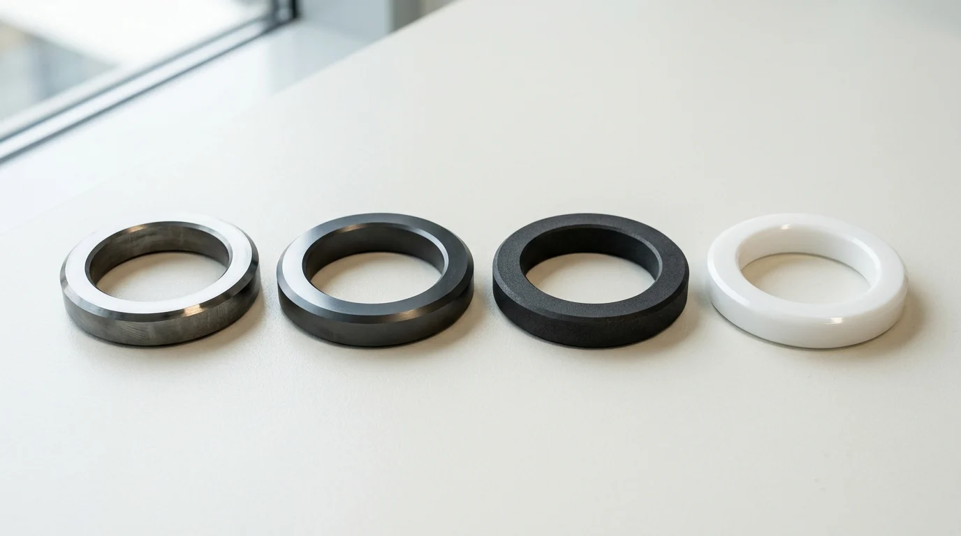
How Seal Face Materials Affect Service Life
Mechanical seals represent the primary barrier against fugitive emissions in rotating equipment, yet they remain the leading cause of centrifugal pump downtime. Industry reliability studies consistently indicate that mechanical seal failures account for 60 to 70 percent of all pump outages. The tribological interface between the primary rotating and stationary faces dictates the operational limits, thermal management, and ultimate longevity of the seal.
Selecting the optimal mechanical seal face materials is not merely a maintenance consideration; it is a fundamental engineering requirement that dictates mean time between failure (MTBF), environmental compliance, and process safety. As industrial processes push toward higher pressures, extreme temperatures, and more aggressive chemical compositions, engineering teams must move beyond generic material selections to deeply analyze the thermodynamic and mechanical properties of the seal interface.
Why material selection matters
The interface between two mechanical seal faces operates in a state of boundary or mixed elastohydrodynamic lubrication. The fluid film separating these highly polished faces is typically less than one micrometer thick. Material selection directly influences how effectively the seal can manage the intense friction and heat generated within this microscopic gap.
If the materials possess insufficient thermal conductivity or inadequate tribological compatibility, the fluid film will vaporize. This leads to dry running, exponential temperature spikes, and catastrophic face destruction. Engineers must match the pressure-velocity (PV) capabilities of the face materials to the application; standard carbon-ceramic pairings may handle PV values up to 100,000 psi-ft/min, whereas highly engineered silicon carbide pairings can operate reliably well beyond 500,000 psi-ft/min under optimized lubrication regimes.
Common failure mechanisms
Understanding how seal faces degrade is essential for specifying materials that resist specific failure modes in the field. Thermal shock is a primary failure mechanism, occurring when localized heat generation causes rapid material expansion, followed by sudden quenching from the process fluid. This sudden temperature delta—often exceeding 150°C in less than a second—can cause severe radial cracking in brittle materials like aluminum oxide ceramics.
Another common mechanism is blister generation, which is particularly prevalent in carbon graphite faces exposed to high-viscosity hydrocarbons. The fluid penetrates the porous carbon matrix, expands rapidly due to frictional heating, and spalls the surface, leaving microscopic craters that destroy the seal’s flatness and leak integrity. Abrasive wear, chemical leaching of metallic binders, and heat-checking are also frequent mechanisms that strictly dictate which material grades can survive in a given process envelope.
Core Mechanical Seal Face Materials
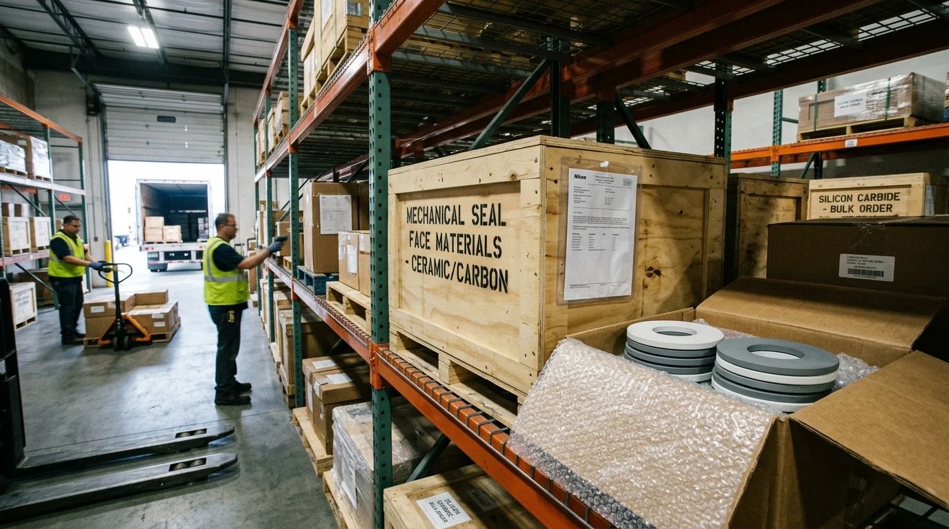
The modern mechanical seal industry relies on a highly engineered portfolio of ceramics, carbides, and carbon composites. While legacy materials like cast iron, bronze, and aluminum oxide still exist in low-duty or legacy applications, high-reliability industrial operations depend almost exclusively on three core material families. Understanding the microstructural differences within these families is critical for accurate specification.
Carbon graphite, silicon carbide, and tungsten carbide
Carbon graphite is the industry standard for the softer, sacrificial face in most hard-versus-soft pairings. It provides exceptional dry-running forgiveness due to its inherent solid-lubricant properties, though it must be impregnated with resins or metals to eliminate natural porosity. Silicon carbide (SiC) represents the premier hard face material, offering extreme hardness, broad chemical inertness, and exceptional thermal conductivity. It is typically available as reaction-bonded (which contains free silicon) or direct-sintered (alpha SiC, which offers superior chemical resistance).
Tungsten carbide (TC) provides extreme toughness and resistance to mechanical shock. Unlike the highly brittle nature of SiC, TC can withstand significant torque transmission and physical impact. However, its metallic binders—usually nickel or cobalt—render it susceptible to chemical leaching in highly corrosive or acidic environments, requiring careful review of fluid compatibility.
Material comparison criteria
When evaluating these core materials, engineers must compare specific physical and thermodynamic properties. Hardness dictates abrasive resistance, while thermal conductivity determines how efficiently frictional heat is transferred away from the fluid film into the bulk process fluid. The coefficient of friction intrinsic to the material pairing dictates the total heat load generated at a given pressure and speed.
| Material | Density (g/cm³) | Hardness (Knoop, kg/mm²) | Thermal Conductivity (W/m·K) | Max Temp Limit (°C) |
|---|---|---|---|---|
| Resin-Impregnated Carbon | 1.8 | 100 (Scleroscope) | 15 | 260 |
| Reaction-Bonded SiC | 3.1 | 2,500 | 150 | 1,350 |
| Direct-Sintered SiC | 3.1 | 2,800 | 120 | 1,400 |
| Nickel-Bound Tungsten Carbide | 14.5 | 1,500 | 80 | 400 |
| Aluminum Oxide (99.5%) | 3.9 | 2,000 | 30 | 1,600 |
This comparative data highlights why silicon carbide has largely displaced aluminum oxide in demanding applications. Its thermal conductivity is approximately four to five times greater, drastically reducing the risk of thermal shock and localized fluid vaporization at the seal interface.
When premium materials are justified
While standard carbon and reaction-bonded SiC cover the majority of industrial applications, extreme conditions justify the procurement of premium, highly engineered surface treatments. Chemical vapor deposition (CVD) diamond coatings represent the apex of seal face technology. By growing a nanocrystalline diamond layer on a silicon carbide substrate, manufacturers achieve a face with a coefficient of friction as low as 0.01—virtually eliminating heat generation.
Although a diamond-coated seal face may cost three to five times more than a standard SiC face, the investment is rapidly justified in applications suffering from frequent dry-running events or poor-lubricity fluids, such as light hydrocarbons and hot boiler feed water. In these challenging services, extending the MTBF by even six months yields massive operational savings that dwarf the initial component cost.
Operating Conditions That Drive Selection
The thermodynamic and chemical properties of the pumped fluid strictly govern the boundary conditions at the mechanical seal interface. A material pairing that provides a ten-year service life in clean, ambient water may fail within hours if misapplied in a high-temperature slurry or a highly volatile hydrocarbon service. Operating conditions are the ultimate arbiter of seal face success.
Abrasive, crystallizing, and corrosive fluids
Process fluids containing suspended solids, abrasives, or crystallizing agents require extreme surface hardness to prevent scoring and grooving. When solids concentration exceeds roughly 5 percent by weight, or when the particulate hardness approaches that of standard pump metallurgy, soft carbon faces are rapidly eroded. In these environments, engineers must specify hard-on-hard pairings, typically SiC/SiC or TC/TC.
Corrosive fluids introduce another constraint: chemical attack on the secondary matrix of the face material. For example, sodium hydroxide and hydrofluoric acid will aggressively attack the free silicon in reaction-bonded SiC, necessitating the use of direct-sintered alpha SiC. Similarly, highly acidic environments require the strict avoidance of cobalt-bound tungsten carbide in favor of highly resistant nickel-bound variants or pure ceramics.
Pressure, speed, and temperature cycling
Dynamic operating conditions—specifically pressure, shaft speed, and temperature cycling—dictate the mechanical strength and thermal shock resistance required from the seal faces. High-pressure applications, typically exceeding 1,000 psig in multistage pipeline injection pumps, subject the seal faces to severe mechanical distortion. If the faces deflect under pressure, the fluid film geometry is compromised, leading to edge loading, massive heat generation, and immediate failure.
Tungsten carbide is frequently selected for high-pressure stationary faces due to its high modulus of elasticity (approximately 600 GPa) and exceptional resistance to pressure-induced distortion. Rapid temperature cycling demands materials with low coefficients of thermal expansion and high thermal conductivity to prevent the propagation of micro-cracks during startup and shutdown sequences.
Hard-versus-soft and hard-versus-hard pairings
The fundamental tribological decision in seal design is whether to deploy a hard-versus-soft or a hard-versus-hard face pairing. Hard-versus-soft pairings, most commonly carbon graphite running against silicon carbide, are the default choice for clean fluids. The carbon face acts as a solid lubricant during transient dry-running conditions and easily conforms to the harder face, establishing an optimal fluid film with minimal frictional heat. However, carbon is easily compromised by abrasives.
Hard-versus-hard pairings (e.g., SiC running against SiC) offer ultimate abrasion resistance but are highly unforgiving. Without a continuous, clean fluid film, a hard-on-hard pairing will generate extreme heat, leading to rapid thermal shock and catastrophic acoustic emissions (squealing). To mitigate this risk in marginal lubrication scenarios, manufacturers often laser-machine micro-hydrodynamic grooves into one of the hard faces to promote fluid film retention and hydrodynamic lift.
Specification and Compliance Requirements
Procurement of mechanical seal face materials extends beyond basic tribological compatibility; it requires strict adherence to industry standards, material traceability, and rigorous quality assurance protocols. In highly regulated sectors such as pharmaceuticals, food processing, and petrochemical refining, material compliance is both a legal and an operational mandate.
Material grades and impregnation options
The base materials utilized in mechanical seals are heavily modified to meet specific operational criteria. Carbon graphite, which is inherently porous, must be impregnated to achieve impermeability and structural integrity. Resin-impregnated carbon is standard for general service, offering broad chemical resistance and a temperature limit of approximately 260°C.
For higher temperature applications, antimony-impregnated carbon elevates the thermal threshold to 400°C and increases the elastic modulus. However, antimony is strictly prohibited in food, beverage, and pharmaceutical applications due to heavy metal toxicity. In those regulated industries, materials must carry FDA and USP Class VI certifications, requiring highly controlled resin binders and direct-sintered ceramics that guarantee zero leaching of process-contaminating particulates.
Industry standards and hazardous-area needs
The petroleum and heavy chemical industries rely heavily on API 682 (ISO 21049), the dominant standard for centrifugal and rotary pump mechanical seals. API 682 4th Edition strictly defines acceptable face materials based on the application category and seal arrangement. For instance, the standard mandates premium, blister-resistant carbon graphite paired with reaction-bonded silicon carbide as the default for Category 1, 2, and 3 seals in standard hydrocarbon service.
Hazardous-area needs also dictate the thermal limits of the seal faces. In explosive atmospheres governed by ATEX directives, the seal face materials must be proven to operate safely below the auto-ignition temperature of the process fluid. This requires precise thermal mapping of the SiC or TC faces under maximum PV conditions to ensure that transient dry-running events do not create an ignition source.
Supplier quality controls and traceability
To ensure reliable performance, the manufacturing tolerances and traceability of seal faces must be flawless. Reputable suppliers provide EN 10204 3.1 material certificates to verify the exact chemical composition and physical properties of the ceramic and carbide batches. Flatness is the most critical quality control metric; seal faces are typically lapped and polished to a flatness of 1 to 2 helium light bands, which is equivalent to a microscopic 0.29 to 0.58 micrometers.
Surface finish (Ra) must also be tightly controlled, usually maintained below 0.15 micrometers for hard faces. This ensures the fluid film can establish itself without microscopic asperities penetrating the boundary layer. Stringent optical flat inspections and interferometry are standard supplier controls required to validate these extreme tolerances before the seal is assembled.
Decision Framework for Engineering Teams
Selecting the correct mechanical seal face materials requires a systematic approach that balances tribological science with operational realities. Engineering teams must navigate complex trade-offs between initial procurement costs, the catastrophic risks of premature failure, and the long-term total cost of ownership (TCO) for the rotating equipment asset.
Step-by-step material selection process
The material selection process must follow a rigorous, step-by-step protocol to prevent misapplication. First, engineers must fully characterize the process fluid, detailing its viscosity, vapor pressure margin, toxicity, and particulate concentration. Second, the operational PV limits must be calculated based on shaft speed, stuffing box pressure, and seal balance ratio. Third, the primary face pairing is selected based on the fluid’s lubricity and abrasive content. Finally, the chosen face materials must be cross-checked against the chemical compatibility of the secondary sealing elements.
| Process Fluid Condition | Recommended Rotating Face | Recommended Stationary Face | Primary Rationale |
|---|---|---|---|
| Clean Water / Light Hydrocarbons | Resin-Impregnated Carbon | Reaction-Bonded SiC | Low friction, excellent dry-run tolerance |
| Heavy Slurry / Mining Tailings | Direct-Sintered SiC | Direct-Sintered SiC | Maximum abrasion and erosion resistance |
| High-Pressure Pipeline (>1,000 psi) | Antimony Carbon | Tungsten Carbide | High modulus resists pressure distortion |
| Caustics / Strong Acids | Direct-Sintered SiC | Direct-Sintered SiC | Zero metallic binders available to leach |
| Flashing Hydrocarbons (Low Margin) | Diamond-Coated SiC | Diamond-Coated SiC | Ultra-low friction prevents fluid vaporization |
This matrix serves as a dependable baseline framework, though localized thermal conditions, duty cycles, and pump vibration profiles may necessitate further material refinement and engineered face topographies.
Using failure analysis to improve choices
Proactive material selection relies heavily on the forensic analysis of failed mechanical seals. When a seal is removed from service, the wear tracks on the primary faces provide a diagnostic map of the operating conditions. A highly polished, uniform wear track indicates stable elastohydrodynamic lubrication. Conversely, deep grooving or a surface roughness (Ra) exceeding 0.5 micrometers indicates boundary lubrication failure and abrasive damage, signaling the need to upgrade from a carbon face to a silicon carbide face.
Heat checking—characterized by fine, localized radial cracks on a hard face—indicates that the fluid film repeatedly vaporized and collapsed. When heat checking is identified during failure analysis, the engineering team must either improve the seal flush plan (API Piping Plan) to lower the stuffing box temperature or upgrade to a face material with significantly higher thermal conductivity, such as diamond-coated SiC.
Balancing service life, risk, and cost
Ultimately, the specification of mechanical seal face materials is an exercise in risk management and life-cycle economics. A standard carbon-versus-ceramic seal may cost $500, while a highly engineered, diamond-coated silicon carbide pairing may easily exceed $2,500. However, in critical path equipment, the component cost of the seal is negligible compared to the cost of downtime, which can easily exceed $10,000 per hour in a continuous process refinery or chemical plant.
Engineering teams must utilize Total Cost of Ownership (TCO) models to justify premium materials. By extending the MTBF from 12 months to 48 months, the elimination of maintenance labor, replacement parts, environmental fines, and lost production drastically outweighs the initial capital expenditure. Balancing service life, risk, and cost requires moving away from commodity purchasing mindsets and treating mechanical seal face materials as critical assets in plant reliability.
Key Takeaways
- Evaluate pressure-velocity limits before selecting seal faces, because standard carbon-ceramic pairs may suit lower-duty service while engineered silicon carbide pairs can handle much higher PV conditions.
- Match face materials to the process fluid, temperature, solids content, and lubrication regime to prevent dry running, thermal cracking, abrasive wear, and chemical attack.
- Use carbon graphite as the sacrificial face in many hard-versus-soft pairings, but assess blister risk in high-viscosity hydrocarbon services.
- Avoid relying on aluminum oxide ceramic in applications with rapid heating and quenching, as temperature changes exceeding 150°C can trigger cracking.
- Treat seal face selection as an engineering reliability decision, since mechanical seal failures are associated with 60 to 70 percent of centrifugal pump outages.
Frequently Asked Questions
Why do mechanical seal face materials affect pump reliability?
Seal faces control friction, heat removal, wear resistance, and fluid film stability. Poor material selection can vaporize the film, cause dry running, and shorten seal life, contributing to pump downtime.
When should silicon carbide be used for mechanical seal faces?
Silicon carbide is preferred for higher PV duties, abrasive fluids, corrosive services, and applications requiring strong thermal conductivity. It often outperforms standard carbon-ceramic pairings in demanding pump services.
What causes carbon graphite seal faces to blister?
Blistering can occur when hydrocarbons penetrate porous carbon, then expand rapidly under frictional heat. The surface can spall, creating small craters that damage flatness and increase leakage.
Are ceramic seal faces suitable for thermal shock conditions?
Aluminum oxide ceramic can be economical, but it is vulnerable to rapid temperature changes. Severe thermal shock may cause radial cracking, so high-temperature or quenching services need careful material review.
What is PV value in mechanical seal selection?
PV means pressure multiplied by velocity. It helps estimate frictional heat and load at the seal faces. Material pairs must be rated for the application’s PV range to avoid overheating and premature failure.

Post time: Aug-06-2026