


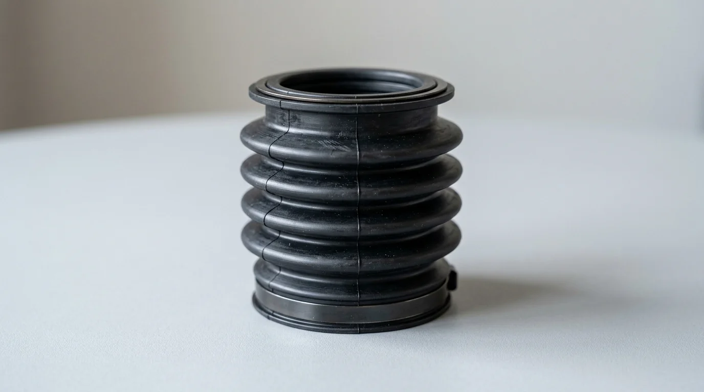
Why Shaft Vibration Causes Rubber Bellows Seal Failure
The integrity of a rubber bellows seal relies heavily on the stability of the rotating equipment it serves. While rubber bellows are inherently designed to accommodate minor shaft runout and thermal expansion, excessive shaft vibration rapidly degrades their mechanical performance. When rotating machinery operates outside acceptable vibration tolerances, dynamic forces exceed the elastomer’s flexibility limits, leading to catastrophic seal failure.
Standard rubber bellows seals are typically engineered to handle 0.15 mm to 0.20 mm of axial movement and minor radial deflection. However, when vibration velocity exceeds 4.5 mm/s RMS (Root Mean Square), continuous dynamic stress induces premature fatigue in the elastomer and disrupts the delicate balance required at the seal faces.
How vibration affects seal faces and bellows
High-frequency vibration fundamentally destabilizes the tribological interface between the primary and mating seal faces. Mechanical seals rely on a microscopic fluid film—usually between 1 and 3 microns thick—to lubricate and cool the sliding faces. Vibration causes face separation or aggressive contact, instantly vaporizing the fluid film and leading to dry running conditions. This results in thermal shock, face blistering, and micro-cracking.
Simultaneously, the rubber bellows absorbs the kinetic energy generated by the vibrating shaft. Continuous flexing beyond the material’s hysteresis limits generates internal friction and localized heat buildup. Over time, this thermo-mechanical degradation causes the elastomer to harden, lose its elasticity, and eventually fracture, destroying the secondary sealing boundary.
Common applications with high vibration risk
Certain industrial environments pose a disproportionately high risk for vibration-induced seal failure due to the nature of the pumped media and operational duty cycles. Wastewater treatment pumps, for example, frequently encounter variable solids loading and ragging, which creates sudden, severe rotor imbalance. Slurry applications similarly suffer from uneven impeller wear, driving up radial vibration over the equipment’s lifecycle.
HVAC chilled water pumps and boiler feed systems are also vulnerable, particularly when operating away from their Best Efficiency Point (BEP). Operating at low flow rates induces internal recirculation and cavitation, generating broadband high-frequency vibration that transfers directly to the seal chamber.
| Vibration Zone (ISO 10816-3) | Velocity (mm/s RMS) | Impact on Rubber Bellows Seal Lifecycle |
|---|---|---|
| Zone A (Newly Commissioned) | < 1.4 | Optimal conditions; maximum MTBF expected. |
| Zone B (Acceptable Long-Term) | 1.4 to 2.8 | Normal wear; bellows elasticity maintained. |
| Zone C (Restricted Operation) | 2.8 to 4.5 | Accelerated elastomer fatigue; fluid film instability. |
| Zone D (Damage Occurring) | > 4.5 | Imminent failure; face chipping and bellows rupture. |
How to Identify Rubber Bellows Seal Failure
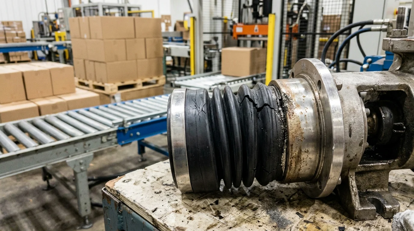
Forensic analysis of a failed rubber bellows seal provides critical insights into the underlying mechanical faults of the pump system. When shaft vibration is the primary failure mechanism, it leaves distinct morphological markers on both the elastomeric and rigid components of the seal assembly. Identifying these markers early prevents misdiagnosing the failure as a chemical incompatibility or thermal overload.
A systematic inspection requires evaluating operational symptoms while the equipment is running and conducting a teardown analysis. Establishing a baseline for normal operation is essential; for instance, a healthy mechanical seal should exhibit zero visible leakage, while a leakage rate exceeding 5 to 10 drops per minute strongly indicates a breached sealing interface requiring immediate investigation.
Key leakage and performance symptoms
The most immediate symptom of vibration-induced failure is intermittent or dynamic leakage. Unlike a static leak—which occurs even when the pump is idle and typically points to a torn bellows or damaged O-ring—dynamic leakage only manifests during operation. This occurs because vibration prevents the seal faces from tracking together, allowing the pumped fluid to escape through the resulting gap.
Another performance indicator is an unexpected rise in seal chamber temperature or excessive motor power consumption. As vibration compromises the lubricating fluid film, the seal faces experience boundary lubrication or dry friction. This generates significant frictional heat, often exceeding the localized boiling point of the fluid, which manifests as a popping sound or visible vapor escaping from the gland.
Seal components to inspect
During a teardown, specific components must be scrutinized for vibration damage. The rubber bellows should be inspected for circumferential cracking, which indicates torsional fatigue, or longitudinal splits caused by a combination of vibration and pressure spikes. The drive band and spring mechanisms often exhibit fretting wear—shiny, polished areas where metal components have rubbed aggressively against each other due to high-frequency micromotion.
The primary and mating faces provide undeniable evidence of vibration. Inspectors should look for edge chipping on carbon or silicon carbide faces, which occurs when the faces physically hammer against one another. Additionally, an uneven or excessively wide wear track on the primary face—for example, a track that is greater than 0.5 mm wider than the mating face—confirms excessive radial shaft movement during operation.
Runout, amplitude, and frequency indicators
Correlating seal damage with specific vibration metrics helps pinpoint the mechanical root cause. Shaft runout, which should strictly remain below the API 682 limit of 0.05 mm TIR (Total Indicator Reading) at the seal face, is a primary metric. Excessive runout forces the seal spring and bellows to constantly adjust with every shaft revolution, rapidly accumulating fatigue cycles.
Vibration amplitude and frequency further refine the diagnosis. High-amplitude, low-frequency vibration (typically 1X the running speed) usually indicates gross rotor imbalance or severe misalignment. Conversely, high-frequency vibration (often >1000 Hz) typically points to advanced bearing degradation, where bearing defects transmit shock pulses directly down the shaft to the mechanical seal faces.
Common Shaft Vibration Sources
Rubber bellows seals rarely fail in isolation; they are typically the weakest link in a mechanically compromised rotating system. To achieve long-term seal reliability, maintenance professionals must look beyond the seal chamber and address the systemic mechanical forces generating the vibration. The seal acts as a highly sensitive indicator of broader equipment health.
Understanding the hierarchy of vibration sources allows for targeted corrective actions. Mechanical forces generated by the rotor, bearings, and structural supports all converge at the seal chamber. When these forces exceed design thresholds—such as maintaining shaft deflection below 0.05 mm (0.002 inches) at the seal face—the resulting kinetic energy guarantees premature seal degradation.
Imbalance, misalignment, and soft foot
Rotor imbalance is one of the most pervasive sources of 1X RPM vibration. Because unbalance forces scale with the square of rotational speed, even minor mass distribution anomalies on the impeller translate into massive radial loads at operating velocity. This constant radial pounding quickly degrades the fluid film between the seal faces.
Misalignment between the pump and motor shafts, as well as soft foot conditions, introduce severe bending moments. Angular misalignment exceeding 0.5 degrees or parallel misalignment greater than 0.05 mm forces the shaft to bow during rotation. A soft foot—where the machine casing distorts when bolted to the baseplate—alters the internal geometry of the seal chamber, preventing the seal faces from maintaining perpendicularity to the shaft axis.
Bearing looseness and shaft deflection
Bearings dictate the radial and axial positioning of the pump shaft. As bearings wear and internal clearances increase, they lose the ability to dampen hydraulic forces. This looseness amplifies initial minor unbalances into severe shaft whip, transmitting chaotic, multi-directional vibration directly to the seal bellows and faces.
The shaft’s flexibility, often represented by its L/D ratio (Length to Diameter), also plays a critical role. Pumps with high L/D ratios are inherently more susceptible to shaft deflection under heavy radial loads, such as when operating near shut-off head. When deflection at the seal face exceeds 0.05 mm, the rubber bellows is forced to act as a secondary bearing, absorbing loads it was never designed to handle.
Axial versus radial vibration effects
Vibration affects the seal differently depending on its directional vector. Radial vibration primarily attacks the fluid film and the rigid faces. Lateral movement causes the primary ring to slide eccentrically against the mating ring, leading to widened wear tracks, edge chipping, and localized heat checking due to uneven fluid film distribution.
Axial vibration, or shaft shuttling, is particularly destructive to the rubber bellows and spring assembly. Mechanical seals are installed with a specific spring compression (typically a working length requiring 3 mm to 5 mm of compression). Severe axial shuttling continuously over-compresses and releases the spring, leading to spring fatigue, while simultaneously subjecting the elastomer bellows to aggressive push-pull forces that rupture the rubber matrix.
| Vibration Source | Typical Frequency | Primary Impact on Rubber Bellows Seal |
|---|---|---|
| Impeller Imbalance | 1X RPM | Radial face tracking errors; widened wear tracks. |
| Misalignment | 1X, 2X RPM | Torsional stress on bellows; uneven face loading. |
| Bearing Defects | High Frequency (Non-synchronous) | Micro-fretting of drive bands; face edge chipping. |
| Pump Cavitation | Broadband / Random | Extreme thermal shock; fluid film vaporization. |
How to Diagnose Vibration Before Seal Replacement
Replacing a failed rubber bellows seal without first diagnosing and mitigating the root cause vibration is a costly exercise in futility. A rigorous diagnostic protocol must be executed while the equipment is still in its operational state, or immediately upon shutdown, to capture accurate mechanical data.
By treating the pump and seal as an integrated dynamic system, technicians can utilize precision measurement tools to quantify the exact nature of the vibration. Establishing a strict diagnostic workflow ensures that critical thresholds—such as overall vibration velocity limits of 3.0 to 4.5 mm/s RMS for standard centrifugal pumps—are evaluated before any new sealing components are installed.
Practical inspection steps
The diagnostic process should begin with a phase-based inspection approach. Phase one involves sensory and operational checks: listening for cavitation or bearing whine, observing the exact location and rate of dynamic leakage, and noting the pump’s position on its performance curve. Operating too far left or right of the Best Efficiency Point (BEP) inevitably induces hydraulic vibration.
Phase two requires static mechanical checks once the equipment is locked out. Technicians must use dial indicators to measure shaft runout, end play, and concentricity of the seal chamber. Phase three involves dynamic vibration analysis under normal load, utilizing accelerometers to capture the vibration spectrum and phase data. This isolates whether the issue is structural, mechanical, or hydraulic.
Priority measurements and tools
Precision tools are non-negotiable for accurate diagnostics. Laser alignment systems should be deployed to ensure shaft alignment falls within a target tolerance of less than 0.03 mm. Relying on straightedges or basic dial indicator reverse-rim methods often leaves residual misalignment sufficient to destroy a new seal over a few months of continuous operation.
Vibration analyzers equipped with piezoelectric accelerometers are essential for capturing high-resolution spectral data. Measurements should be taken at the bearing housings in the horizontal, vertical, and axial planes. High-end analyzers can separate the overall vibration velocity (measured in mm/s or in/s RMS) into specific frequency bins, allowing analysts to differentiate between a 1X RPM imbalance and high-frequency bearing cage defects.
How to document failure evidence
Documenting failure evidence systematically is crucial for long-term reliability engineering. Data collection should follow a standardized template that records the operational context at the time of failure, including fluid temperature, suction and discharge pressures, and the recorded vibration spectra.
Physical evidence from the failed seal must also be preserved. Technicians should photograph the condition of the rubber bellows, the spring mechanism, and the seal faces immediately upon removal. Examining the carbon or silicon carbide faces under 10x to 50x magnification can reveal micro-cracking, blistering, or wear patterns that corroborate the vibration data collected during the dynamic analysis phase.
Repair, Redesign, or Replace the Seal
Once the failure mechanism has been confirmed as vibration-induced, plant engineers face a critical decision: repair the existing setup, redesign the sealing arrangement, or replace the equipment entirely. This decision must balance immediate maintenance costs against the long-term impacts of equipment downtime and process safety.
The path forward depends heavily on the severity of the mechanical degradation and the feasibility of correcting the root cause. If the underlying vibration can be permanently reduced below the critical threshold of 3.0 mm/s RMS, standard sealing solutions can be retained. However, if systemic issues persist, engineering out the vulnerability through seal redesign becomes the most viable financial option.
When like-for-like replacement is acceptable
A like-for-like replacement of a rubber bellows seal is only acceptable under stringent conditions. Specifically, it should only be executed if the root cause of the vibration has been definitively identified and permanently eliminated. For example, if the vibration was traced to a single degraded bearing or a fouled impeller, and those components have been replaced and balanced (e.g., to an ISO G2.5 balance grade), installing the same seal type is appropriate.
Furthermore, the historical Mean Time Between Failures (MTBF) should be evaluated. If the pump historically achieved an MTBF of greater than 24 to 36 months before this isolated failure, the original seal design is likely adequate for the application. If the MTBF is consistently under 12 months, like-for-like replacement is a poor investment.
Corrective actions for vibration control
Implementing corrective actions to control vibration requires a comprehensive mechanical overhaul. This often involves upgrading the pump foundation and baseplate to increase structural mass and rigidity, thereby dampening sympathetic resonance. Correcting pipe strain is also critical; pipe flanges must align with pump flanges to within 0.25 mm before any bolts are tightened, ensuring no external stress distorts the pump casing.
Dynamic balancing of the rotating assembly is another mandatory corrective action. Rotors should be balanced in two planes to meet or exceed OEM specifications. Additionally, if the pump is operating off-curve, variable frequency drives (VFDs) or impeller trimming should be utilized to bring the operation closer to the Best Efficiency Point, drastically reducing hydraulically induced vibration.
How to prevent repeat seal failure
Preventing repeat seal failures requires a combination of proactive maintenance and potential hardware upgrades. If vibration cannot be fully mitigated due to process variables, upgrading from a standard single-spring rubber bellows to a balanced multi-spring seal or a stationary metal bellows design may be necessary. These designs offer superior ability to handle face tracking under moderate vibration, though rubber bellows remain highly cost-effective if equipment health is rigorously maintained.
The ultimate prevention strategy is the implementation of continuous condition monitoring. Installing IoT-enabled vibration sensors on the pump bearing housings allows maintenance teams to track vibration trends in real-time. By setting automated alert thresholds at 4.0 mm/s RMS, operators can intervene, schedule maintenance, and correct mechanical imbalances long before the vibration amplitude reaches the critical level that destroys the rubber bellows seal.
Key Takeaways
- Keep shaft vibration below 2.8 mm/s RMS where possible to support long-term rubber bellows seal life and stable face lubrication.
- Treat vibration above 4.5 mm/s RMS as a damage condition because it can rapidly cause bellows rupture, seal face chipping, and dry running.
- Check whether the pump is operating near its Best Efficiency Point, since low-flow operation can create recirculation, cavitation, and high-frequency vibration.
- Inspect failed seals for hardened elastomer, cracks, uneven face wear, and chipped faces before assuming the root cause is chemical incompatibility.
- Use rubber bellows seals only within their typical axial movement capability of about 0.15 mm to 0.20 mm and correct the mechanical source of excess runout.
Frequently Asked Questions
How much shaft movement can a rubber bellows seal normally tolerate?
Most standard rubber bellows seals are designed for minor shaft runout, about 0.15 mm to 0.20 mm of axial movement, plus limited radial deflection. Exceeding these limits accelerates elastomer fatigue and seal face instability.
At what vibration level does seal failure become likely?
When vibration velocity exceeds about 4.5 mm/s RMS, the equipment enters a damage zone where face chipping, fluid film collapse, bellows hardening, and rupture can occur quickly.
Why does vibration damage the seal faces?
Mechanical seal faces depend on a very thin lubricating fluid film, often 1 to 3 microns. Vibration disrupts this film, causing alternating face separation and heavy contact, which can lead to dry running, heat, cracking, and blistering.
Which pump applications are most at risk for vibration-related bellows failure?
Wastewater pumps, slurry pumps, HVAC chilled water pumps, and boiler feed systems are common high-risk applications, especially when solids, cavitation, impeller imbalance, or operation away from the Best Efficiency Point are present.
How can I tell if vibration caused a rubber bellows seal failure?
Look for elastomer hardening, cracking, bellows rupture, uneven face wear, chipping, or micro-cracks. These signs often indicate dynamic stress rather than simple chemical attack or temperature overload.

Post time: Aug-27-2026