


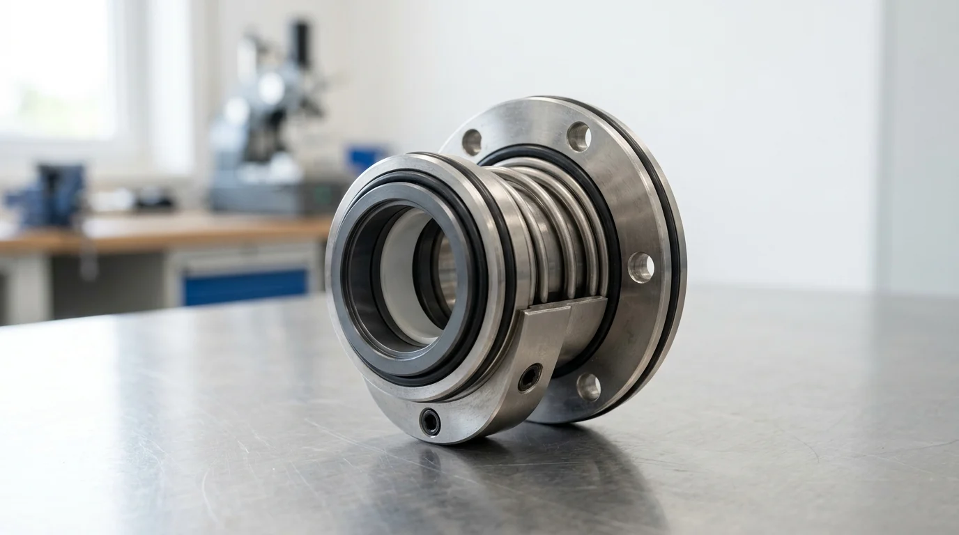
How Pump Vibration Causes Mechanical Seal Leakage
Mechanical seals are precision-engineered components designed to operate with a microscopic fluid film between the primary mating faces. This lubricating film, typically ranging from 0.5 to 2.0 microns in thickness, is essential for minimizing friction, dissipating heat, and preventing direct contact between the stationary and rotating faces. Because this operational tolerance is exceptionally tight, mechanical seals are highly susceptible to external dynamic forces. When a pump experiences excessive vibration, the kinetic energy is transmitted directly through the shaft and casing to the seal chamber.
The transmission of these vibratory forces disrupts the delicate fluid film equilibrium. According to ISO 10816-7 standards for rotodynamic pumps, vibration velocities exceeding 4.5 mm/s RMS generally indicate a compromised mechanical state. At elevated vibration levels, the seal faces are subjected to rapid mechanical shocks, leading to face separation, fluid film vaporization, and ultimately, premature fluid leakage. Understanding the exact mechanisms by which vibration degrades these precision barriers is the first step in extending Mean Time Between Failures (MTBF) for industrial pumping systems.
Why Vibration-Related Leakage Should Be Treated as a Warning
Sign
In industrial fluid handling, a leaking mechanical seal is rarely an isolated component defect; rather, it is a prominent symptom of broader systemic instability. When vibration induces seal leakage, it signals that the rotor dynamics of the pump have degraded beyond acceptable operational thresholds. Treating the leak by simply replacing the seal without addressing the underlying vibration effectively guarantees a recurrence of the failure.
If vibration levels reach or exceed 7.1 mm/s RMS (falling into ISO 10816 Zone D), the mechanical seal acts as a structural fuse. The resulting leakage warns operators of severe issues such as bearing degradation, shaft deflection, or critical structural resonance. Ignoring this warning sign not only leads to excessive fugitive emissions and product loss but also risks catastrophic pump failure, where the rotating assembly makes contact with the stationary casing, resulting in tens of thousands of dollars in secondary damage.
Operating Conditions That Increase Seal Leakage Risk
The operating conditions of a pump dictate the hydraulic forces exerted on the rotor, which directly influence vibration levels. Pumps are designed to operate optimally at their Best Efficiency Point (BEP). When a pump operates outside its Preferred Operating Region (POR)—typically defined by API 610 as between 70% and 120% of BEP—radial loads on the impeller increase exponentially. This hydraulic imbalance translates into radial shaft vibration, forcing the mechanical seal faces out of alignment.
Operating conditions such as excessive discharge pressure, high fluid temperatures, and fluctuating suction pressures also elevate leakage risk. For example, pumping fluids near their vapor pressure without an adequate Net Positive Suction Head available (NPSHa) margin (typically requiring at least a 1.0 to 1.5 meter margin over NPSHr) induces cavitation. The implosion of vapor bubbles generates high-frequency, high-energy shocks that propagate directly to the seal chamber, shattering the carbon faces or fracturing the tungsten carbide components.
Key Mechanical Seal Parts and Vibration Mechanisms
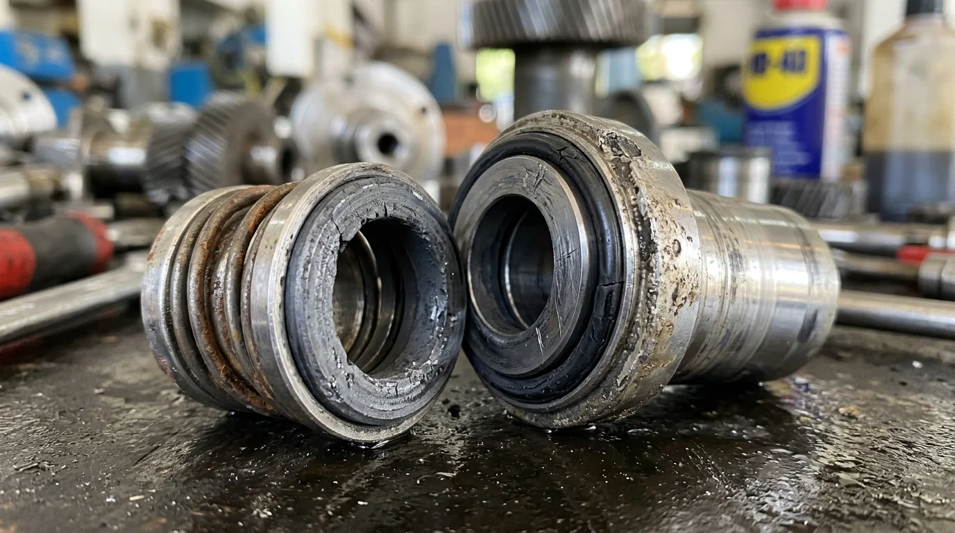
A mechanical seal is an assembly of rigid and flexible components working in unison to accommodate minor shaft movements while maintaining a hermetic barrier. To achieve this, the primary seal faces are lapped to an extraordinary flatness, typically measured at 1 to 3 helium light bands (approximately 0.3 to 0.9 microns). Because the seal relies on such exact geometry, understanding how specific vibration mechanisms interact with individual seal components is critical for failure analysis.
Vibration does not affect all seal parts equally. The frequency, amplitude, and directional vector of the vibration dictate which components will yield first. Recognizing these interactions allows reliability engineers to trace the physical damage on a failed seal back to the specific dynamic anomaly that caused it.
Seal Faces, Secondary Seals, Springs, and Gland Plates
The primary seal faces (commonly manufactured from Silicon Carbide, Tungsten Carbide, or Carbon Graphite) are brittle and highly vulnerable to mechanical shock. High-frequency vibration can cause edge chipping or micro-cracking across the face profile. The secondary seals, which include O-rings, V-rings, and PTFE wedges, are responsible for sealing the gap between the rigid seal components and the pump shaft or casing. Under continuous vibration, these elastomers experience fretting—a phenomenon where micro-movements (as small as 0.1 mm) scour the shaft sleeve, degrading the elastomer and causing secondary leakage.
Springs and bellows provide the closing force necessary to keep the faces together during pressure fluctuations. Whether utilizing multiple coil springs, a single wave spring, or a welded metal bellows, these components are subject to fatigue failure when exposed to severe axial vibration. Finally, the gland plate, which bolts the stationary seal components to the pump casing, can suffer from loosening torque or distortion if casing vibration exceeds structural limits.
Vibration Terms Used in Seal Failure Analysis
To accurately diagnose seal failures, vibration data must be quantified using specific metrics. Amplitude measures the severity of the vibration, while frequency indicates the root cause based on the rotational speed (RPM) of the shaft. Phase analysis helps determine the relative motion between different parts of the pump.
| Vibration Metric | Common Unit of Measurement | Impact on Mechanical Seal Integrity |
|---|---|---|
| Displacement | Mils (0.001 inches) or Microns (µm) | Indicates low-frequency movement; high displacement causes O-ring fretting and spring fatigue. |
| Velocity | in/s peak or mm/s RMS | Best overall indicator of fatigue; directly correlates to the destruction of the fluid film. |
| Acceleration | g’s (gravitational force) | Highlights high-frequency shocks (like cavitation); leads to face chipping and brittle fracture. |
Understanding whether a vibration issue is displacement-dominant (low frequency, high movement) or acceleration-dominant (high frequency, high impact) guides the inspector to look for specific wear patterns on the seal faces and elastomers.
Radial Shaft Movement vs Axial Shaft Movement
The direction of the vibratory force dictates the failure mode of the mechanical seal. Radial shaft movement occurs perpendicular to the shaft centerline. When radial deflection exceeds 0.05 mm (0.002 inches) at the seal chamber, the rotating face is forced off-center from the stationary face. This eccentric motion wipes away the lubricating fluid film, causing dry running, localized heat generation, and thermal cracking (heat checking) on the seal faces.
Axial shaft movement occurs parallel to the shaft centerline. Excessive end-play (axial movement greater than 0.1 mm) forces the seal springs or bellows to rapidly compress and expand. This axial oscillation leads to a phenomenon known as “hammering,” where the seal faces repeatedly impact each other. Over time, this hammering shatters the brittle face materials and causes fatigue cracking in the welded convolutions of metal bellows seals.
Common Pump Vibration Causes That Damage Mechanical Seals
Vibration in centrifugal pumps is rarely spontaneous; it is the physical manifestation of mechanical, hydraulic, or operational defects. To protect mechanical seals, facilities must identify and eliminate the root causes of these dynamic forces. Industry standards, such as balancing impellers to ISO 1940-1 Grade G2.5 or G6.3, exist precisely to minimize these destructive inputs.
The forces that damage mechanical seals can be broadly categorized. By matching the vibration frequency signature to common pump defects, maintenance teams can isolate the exact mechanism tearing the seal apart.
Imbalance, Misalignment, Soft Foot, and Looseness
Mechanical imbalance is a leading cause of 1X RPM radial vibration. When the center of mass of the rotating assembly does not align with the center of rotation, it generates a centrifugal force that bends the shaft. This deflection directly translates to radial runout at the seal faces. Similarly, shaft misalignment between the pump and the motor generates both 1X and 2X RPM vibration peaks. If angular or parallel misalignment exceeds tolerances (typically > 0.05 mm TIR), it imposes severe bending moments on the shaft.
Soft foot—a condition where the pump or motor feet do not sit flat on the baseplate—causes casing distortion when the mounting bolts are tightened. A soft foot condition exceeding 0.05 mm (0.002 inches) can twist the pump volute, throwing the seal chamber out of concentricity with the shaft. Mechanical looseness in the bearing housings or baseplate further amplifies these forces, allowing the entire rotating assembly to oscillate uncontrollably.
Cavitation, Recirculation, and Other Hydraulic Forces
Hydraulic forces are equally destructive to mechanical seals. Cavitation, caused by insufficient NPSHa, produces broadband, high-frequency vibration (often exceeding 1000 Hz) as vapor bubbles violently collapse against the impeller vanes. This shockwave travels down the shaft, causing micro-chipping on the primary seal faces and shattering the fluid film.
Flow recirculation occurs when a pump operates significantly below its BEP (e.g., below 60% of design flow). The fluid fails to exit the impeller cleanly, creating internal vortices and pressure pulsations. These pulsations exert random, low-frequency hydraulic loads on the impeller, causing the shaft to whip radially. This whipping action forces the seal faces to open and close rapidly, inviting abrasive particles into the sealing gap and accelerating wear.
Mechanical vs Hydraulic vs Operational Causes
Differentiating between mechanical, hydraulic, and operational causes requires spectrum analysis. Mechanical issues are typically continuous and tied directly to the running speed, whereas hydraulic issues often fluctuate with process conditions.
| Cause Category | Specific Defect | Typical Frequency Signature | Primary Threat to Mechanical Seal |
|---|---|---|---|
| Mechanical | Rotor Imbalance | 1X RPM | Constant radial deflection; fluid film wipe. |
| Mechanical | Misalignment | 1X, 2X, sometimes 3X RPM | Shaft bending; uneven face wear and O-ring fretting. |
| Hydraulic | Cavitation | Broadband, High Frequency (>1000 Hz) | Severe shock loads; fractured faces and brittle failure. |
| Operational | Dead-heading (Zero Flow) | Vane Pass Frequency (Number of Vanes × RPM) | Extreme heat buildup; elastomer extrusion and face vaporization. |
By classifying the vibration source, engineers can determine whether the solution requires mechanical correction (precision balancing), system redesign (NPSH improvement), or operational changes (implementing minimum flow bypass lines).
How to Reduce Mechanical Seal Leakage Caused by Pump Vibration
Mitigating mechanical seal leakage requires a proactive strategy that eliminates destructive dynamic forces and fortifies the seal’s operating environment. The goal is to reduce radial and axial shaft movement to absolute minimums, ensuring the seal faces remain perfectly parallel. While standard maintenance practices offer a baseline of reliability, achieving extended MTBF requires precision execution.
Investments in precision maintenance directly correlate to reduced seal consumption. For instance, reducing overall pump vibration from 6.0 mm/s to 2.5 mm/s RMS can frequently double or triple the operational lifespan of a mechanical seal, drastically reducing downtime and replacement costs.
Balancing, Precision Alignment, and Baseplate Correction
The foundation of vibration reduction is precision balancing and alignment. Rotating assemblies, including impellers and couplings, should be dynamically balanced to an ISO 1940-1 Grade of G2.5, rather than the standard G6.3, to minimize residual unbalance forces. Laser alignment systems must be utilized to align the pump and motor shafts to tolerances tighter than 0.03 mm (0.001 inches), virtually eliminating coupling-induced radial loads.
Baseplate integrity is equally vital. Following API 610 installation practices, baseplates must be rigidly grouted to a concrete foundation with a mass at least three to five times that of the pump and motor assembly. This massive foundation acts as a vibration sink, dampening resonant frequencies. Furthermore, all soft foot conditions must be shimmed and corrected to below 0.05 mm prior to final alignment to prevent volute distortion.
Seal Selection and Seal Support Plan Improvements
When process conditions inherently generate vibration, upgrading the mechanical seal design and its support system (API Plans) is necessary. For pumps operating at high rotational speeds (e.g., face velocities exceeding 25 m/s), transitioning from a rotating spring design to a stationary spring design is highly recommended. Stationary springs isolate the flexible components from the rotational forces, making the seal immune to shaft-induced centrifugal distortion.
Improving the seal environment via API flush plans also mitigates vibration-induced damage. Implementing an API Plan 53A (pressurized dual seal system) provides a pristine, high-lubricity barrier fluid between the seal faces, ensuring a stable fluid film even if the pump experiences temporary cavitation or dry-running. For high-temperature applications, utilizing a Plan 23 (recirculation through a cooler) prevents the fluid from vaporizing at the seal faces, thereby eliminating localized thermal shocks.
Choosing Between Repair, Redesign, and Replacement
When faced with chronic vibration and seal failure, facilities must evaluate whether to repair the existing setup, redesign the pump dynamics, or replace the equipment. If a pump features a high shaft stiffness ratio (L³/D⁴, where L is the overhung length and D is the shaft diameter), it will inherently deflect under load. If calculations show radial deflection exceeding 0.05 mm at the seal faces during normal operation, standard repairs will not suffice.
In such cases, redesigning the system by upgrading to a larger diameter solid shaft, or changing from a single-volute to a double-volute casing to balance hydraulic radial loads, becomes necessary. While redesign or total replacement carries a higher initial capital expenditure, the Return on Investment (ROI) is rapidly achieved through the elimination of chronic mechanical seal replacements, reduced fugitive emissions, and the stabilization of plant production.
Key Takeaways
- Treat mechanical seal leakage as a symptom of pump instability, not just a seal defect, and investigate vibration before installing a replacement seal.
- Monitor pump vibration against ISO 10816-7 guidance, because readings above 4.5 mm/s RMS can indicate conditions that threaten seal face stability.
- Keep pumps within the preferred operating region, typically 70% to 120% of BEP, to reduce radial shaft loads and seal face misalignment.
- Maintain at least a 1.0 to 1.5 meter NPSHa margin over NPSHr where applicable to reduce cavitation-related shock damage to seal faces.
- Inspect bearings, shaft runout, alignment, foundation looseness, and resonance when seal leakage appears repeatedly after replacement.
Frequently Asked Questions
Why does pump vibration make a mechanical seal leak?
Excessive vibration transfers shock through the shaft and seal chamber, disturbing the 0.5–2.0 micron fluid film between seal faces. This can cause face separation, heat buildup, vaporization, wear, and visible leakage.
What vibration level is dangerous for pump mechanical seals?
For rotodynamic pumps, ISO 10816-7 indicates that vibration above about 4.5 mm/s RMS can signal a compromised mechanical condition. Levels near or above 7.1 mm/s RMS require urgent investigation.
Should I replace the seal immediately if it starts leaking?
A replacement seal may stop leakage temporarily, but it will likely fail again if vibration causes are not corrected. Check bearings, alignment, shaft runout, cavitation, resonance, and operation away from BEP before restarting.
How does operating away from BEP affect seal life?
Running outside the preferred operating region, often 70%–120% of BEP under API 610 guidance, increases radial hydraulic loads on the impeller. This can bend the shaft, misalign seal faces, and accelerate leakage.
Can cavitation damage mechanical seals?
Yes. Cavitation creates high-frequency shock waves when vapor bubbles collapse. These shocks can chip carbon faces, crack hard-face materials, destabilize the seal film, and increase vibration at the seal chamber.

Post time: Jul-25-2026