


Why Early Mechanical Seal Warning Signs Matter
In industrial fluid-handling systems, mechanical seals serve as the primary containment barrier between the rotating shaft and the stationary pump casing. Their operational integrity directly dictates the reliability, safety, and environmental compliance of the entire pumping unit. In high-stakes environments such as hydrocarbon processing, chemical manufacturing, and power generation, seal performance is governed by strict parameters, often adhering to standards like API 682, which mandates a minimum of 25,000 hours of continuous operation without requiring maintenance.
Despite these rigorous design standards, mechanical seals remain one of the most frequent points of failure in centrifugal pumps, accounting for approximately 65% to 70% of all pump maintenance interventions. Recognizing the early warning signs of seal degradation is not merely a maintenance best practice; it is a critical operational mandate. Intervening before a seal breaches its operational thresholds prevents minor mechanical deviations from escalating into catastrophic equipment failures.
What a mechanical seal does in industrial equipment
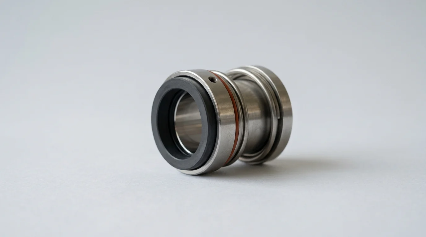
At a fundamental level, a mechanical seal restricts fluid leakage by maintaining a highly controlled, microscopic gap between two exceptionally flat surfaces: a rotating primary ring and a stationary mating ring. These faces are lapped to a flatness tolerance of 2 to 3 light bands, which equates to roughly 11.6 to 17.4 microinches. A thin fluid film—typically between 0.5 and 1.5 microns thick—migrates between these faces to provide essential lubrication and cooling.
Beyond the primary sealing faces, the assembly relies on secondary static seals, such as elastomeric O-rings or flexible graphite wedges, to prevent leakage along the shaft and casing. Mechanical loading elements, including single coil springs, multiple springs, or welded metal bellows, apply constant axial force to keep the seal faces closed during dynamic pressure changes. Together, these components must dynamically adjust to microscopic axial and radial shaft movements while handling fluid pressures that can exceed 1,000 PSI (69 bar) in severe applications.
Risks of ignoring early seal deterioration
Ignoring the initial indicators of seal deterioration introduces severe operational and environmental liabilities. When the microscopic fluid film breaks down or the seal faces sustain mechanical damage, the resulting friction generates extreme localized heat. This thermal escalation can cause elastomeric secondary seals to harden, crack, or extrude, leading to rapid loss of containment. In applications handling volatile organic compounds (VOCs), this translates to hazardous emissions that can quickly exceed the EPA’s strict 500 ppm threshold for fugitive emissions.
Furthermore, unchecked seal degradation frequently cascades into secondary mechanical damage. A compromised seal allows process fluid to migrate along the shaft, contaminating the bearing housing. Studies indicate that process fluid contamination as low as 0.002% in bearing lubricating oil can reduce bearing life by up to 48%. If the bearing fails, the resulting shaft deflection will destroy the remaining seal components, potentially damaging the pump casing and impeller, exponentially multiplying the repair scope.
How early detection reduces downtime and cost
Proactive detection of mechanical seal wear fundamentally alters the economic profile of pump maintenance. Replacing a mechanical seal on a scheduled basis allows procurement teams to source parts without expediting fees and enables operations to switch to standby equipment without interrupting production flow. A planned cartridge seal replacement for a standard ANSI process pump typically incurs a direct cost of $1,500 to $3,500 and requires four to six hours of labor.
Conversely, a run-to-failure event triggers emergency shutdowns, which carry staggering financial penalties. In a continuous petrochemical process, an unplanned pump outage can result in lost production costs ranging from $10,000 to over $100,000 per hour. By leveraging early detection, reliability engineers can transition from reactive firefighting to predictive maintenance, effectively doubling the Mean Time Between Failures (MTBF) and slashing total lifecycle maintenance costs by an estimated 30% to 40%.
Process Conditions That Lead to Seal Failure
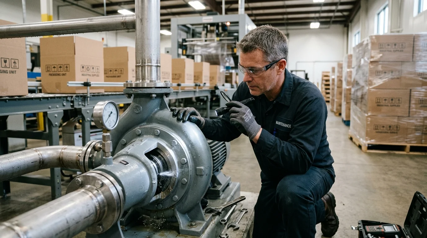
Mechanical seals rarely fail in isolation; their degradation is almost always a symptom of adverse process conditions or systemic mechanical deficiencies. A seal is designed to operate within a specific envelope of pressure, temperature, and fluid state. When the process strays beyond these engineered boundaries, the delicate balance of the fluid film is disrupted, precipitating rapid wear.
Understanding the specific operational stressors that attack mechanical seals is the first step in diagnosing premature wear. Reliability engineers must continuously monitor hydraulic stability, fluid composition, and mechanical alignment to ensure the seal environment remains conducive to long-term operation.
Pressure instability, dry running, and cavitation
Hydraulic instability is a primary driver of seal face damage. When a pump operates away from its Best Efficiency Point (BEP), it experiences unbalanced radial and axial forces that cause shaft deflection, forcing the seal faces to open and close rapidly. If the Net Positive Suction Head available (NPSHa) drops below the required margin (NPSHr), cavitation occurs. The implosion of vapor bubbles generates shockwaves that shatter the fragile carbon or silicon carbide seal faces.
Dry running is equally destructive. It occurs when the pump loses prime, or when the process fluid vaporizes between the seal faces due to inadequate vapor pressure margins. Without the lubricating fluid film, the coefficient of friction spikes. Face temperatures can surge by 150°C (300°F) within 30 to 60 seconds of dry running, causing heat checking—a network of microscopic radial cracks on the seal faces that act like cutting tools against the opposing ring.
Abrasive, crystallizing, or corrosive fluids
The physical and chemical properties of the pumped media heavily influence seal longevity. Abrasive slurries with solid concentrations exceeding 10% by weight require specialized hard-face combinations, such as silicon carbide versus tungsten carbide, to resist abrasive grooving. If the fluid contains dissolved solids that crystallize upon contact with the atmosphere, the resulting crystals can pack into the dynamic O-ring grooves, causing seal hang-up and preventing the springs from closing the seal faces.
Corrosive fluids attack the metallurgy of the seal components. Incorrect material selection can lead to pitting or chloride stress corrosion cracking in 316 stainless steel bellows or springs. Furthermore, chemical incompatibility with elastomeric O-rings can cause them to swell by 20% to 30% of their original volume, or conversely, to shrink and embrittle, destroying the secondary sealing barrier.
Installation, alignment, and lubrication issues
Even the most robust mechanical seal will fail prematurely if installed on structurally compromised equipment. API 682 guidelines dictate that radial shaft runout must not exceed 0.002 inches (0.05 mm) Total Indicator Reading (TIR) at the seal chamber. Excessive runout, often caused by bent shafts or degraded bearings, forces the seal components to cycle dynamically with every rotation, leading to fatigue failure of the metal bellows or springs.
Pipe strain is another hidden culprit. When heavy suction or discharge piping is bolted to the pump flanges without proper support, the mechanical stress distorts the pump casing. This distortion misaligns the seal chamber relative to the rotating shaft. Additionally, inadequate lubrication of the pump bearings increases mechanical vibration, which is directly transmitted to the seal faces, accelerating wear and chipping.
Observable Symptoms of Seal Deterioration
Because mechanical seals are enclosed within the pump housing, operators cannot visually inspect the sealing faces during operation. However, the degradation of internal components reliably produces external symptoms. By establishing precise baselines for normal operation, maintenance teams can identify the subtle physical manifestations of seal wear long before a total breach occurs.
Monitoring these observable symptoms requires a combination of routine operator rounds, automated sensor data, and a clear understanding of acceptable operational thresholds. Changes in leakage rates, acoustic signatures, and auxiliary system behaviors serve as the primary indicators of impending failure.
Leakage beyond normal seal weeping
It is a common misconception that mechanical seals operate with zero leakage. To maintain the lubricating fluid film, a microscopic amount of fluid must cross the seal faces. In a healthy seal, this fluid typically vaporizes upon reaching the atmospheric side, resulting in unobservable leakage (often less than 3 grams per hour for light hydrocarbons). Visible liquid dripping from the seal gland is an immediate red flag.
When assessing leakage, operators must quantify the rate to determine the severity of the degradation. A transition from a dry gland to a slow weep (1 to 5 drops per minute) suggests initial face damage or O-ring degradation. A steady drip or a continuous stream indicates a total loss of face contact or a ruptured secondary seal.
| Seal Condition | Leakage Rate (Liquid Process) | Emission Rate (VOC Process) | Required Action |
|---|---|---|---|
| Normal Operation | Invisible (vaporizes), < 3 g/hr | < 50 ppm | Monitor baseline |
| Early Warning | 1 to 5 drops per minute | 100 – 500 ppm | Schedule inspection within 14 days |
| Advanced Wear | 10 to 30 drops per minute | 500 – 1,000 ppm | Plan shutdown/repair within 48 hours |
| Critical Failure | Continuous stream | > 10,000 ppm | Immediate emergency shutdown |
Vibration, noise, heat, and power draw changes
Mechanical anomalies at the seal faces frequently alter the pump’s acoustic and vibratory signatures. A high-pitched squealing or “popping” noise emanating from the seal chamber strongly indicates fluid vaporization or dry running. As the seal faces rub without adequate lubrication, the increased friction forces the electric motor to draw more current. A sustained 5% to 10% increase in motor amperage, absent any changes in flow or head requirements, often points to severe seal face friction.
Vibration analysis provides an even clearer picture. While low-frequency vibrations (1X or 2X running speed) typically point to unbalance or misalignment, seal face damage generates high-frequency acoustic emissions. Furthermore, excessive friction generates heat. If thermographic scans reveal that the seal gland temperature is consistently 15°C to 20°C (27°F to 36°F) higher than the surrounding pump casing, the fluid film is likely failing, and the faces are in direct mechanical contact.
Flush, quench, barrier fluid, and seal pot abnormalities
For dual mechanical seals, the auxiliary flush, quench, or barrier fluid systems (e.g., API Plans 52, 53A/B/C, or 54) function as the life support system and the primary diagnostic window. In an API Plan 53A pressurized barrier system, the barrier fluid is maintained at a pressure 1.5 to 2.0 bar (22 to 29 PSI) higher than the seal chamber pressure. A healthy system may lose a minute amount of barrier fluid over a month.
If operators must replenish the seal pot more frequently than once a week, or if the system experiences a pressure drop exceeding 0.5 bar (7.2 PSI) over a 24-hour period, the inboard or outboard seal faces are compromised. Conversely, in an unpressurized API Plan 52 system, a sudden increase in seal pot liquid level or a rapid spike in the pot’s pressure gauge indicates that the inboard seal has failed, allowing high-pressure process fluid to flood the buffer system.
How to Diagnose Warning Signs
Once a warning sign is detected, maintenance and reliability teams must transition from observation to diagnosis. Accurate diagnosis prevents the common error of replacing a failed seal without addressing the underlying systemic issue, which inevitably leads to repeat failures.
Diagnostic precision relies on correlating physical symptoms with process data and historical maintenance records. By triangulating these data points, engineers can isolate whether the root cause is mechanical, operational, or chemical in nature.
Match symptoms to likely root causes
The first step in diagnostics is mapping the observed physical symptoms to their most probable failure modes. This logical deduction allows teams to prepare the correct replacement components and address auxiliary system issues before taking the pump offline. For example, if a seal is leaking and leaving a heavy accumulation of fine black carbon dust around the gland, the primary diagnosis is severe dry running of a carbon face.
Similarly, if the seal exhibits intermittent heavy leakage that temporarily resolves itself, the likely cause is O-ring hang-up due to fretting or crystallization, rather than shattered seal faces.
| Observed Symptom | Likely Root Cause | Diagnostic Verification |
|---|---|---|
| Carbon dust around gland | Dry running / Lack of lubrication | Check vapor pressure margin and flush flow |
| Intermittent heavy leakage | Dynamic O-ring hang-up | Inspect for shaft fretting or fluid crystallization |
| Squealing noise / High heat | Fluid vaporization at seal faces | Verify flush temperature and process cooling |
| Barrier fluid pressure loss | Inboard or outboard face wear | Check API Plan 53 pot pressure trends |
| High-frequency vibration | Face rubbing or chipping | Perform PeakVue or ultrasonic analysis |
Use vibration, thermography, and process trend data
Advanced condition monitoring technologies provide the quantitative data required to confirm diagnostic hypotheses. High-frequency vibration enveloping, such as PeakVue technology, can isolate the specific stress waves generated by microscopic seal face impacting, separating them from background pump noise. This allows analysts to detect face chipping weeks before volumetric leakage occurs.
Infrared (IR) thermography is equally valuable. By mapping the thermal gradient across the seal gland and flush piping, technicians can verify if the API flush plan is functioning. For instance, in an API Plan 11 (discharge bypass to seal), if the flush line temperature is identical to the ambient air rather than the process fluid, the orifice is likely plugged, starving the seal of cooling flow and confirming the cause of overheating.
Review inspection and maintenance records
Diagnostic accuracy is heavily dependent on historical context. Reliability engineers must interrogate the Computerized Maintenance Management System (CMMS) to review the MTBF and past failure modes of the specific asset. If a pump requires a new mechanical seal every six months, and the tear-down reports consistently cite “extruded O-rings,” the diagnosis shifts from a mechanical alignment issue to an incorrect material specification (e.g., using Viton in a high-temperature steam application instead of Kalrez).
Reviewing process trend data from the SCADA or DCS systems during the exact time the symptoms first appeared is also critical. Often, a seal failure can be traced back to a specific operational upset, such as a sudden loss of suction pressure, a rapid temperature spike, or a period where the pump was run against a closed discharge valve. Identifying these process anomalies confirms whether the seal failure was induced by an operational error rather than a component defect.
Decision Path for Maintenance Teams
When warning signs are confirmed, maintenance leadership must execute a calculated response. The decision-making process must balance the immediate need to maintain production with the risk of catastrophic equipment damage and environmental non-compliance.
Establishing a formalized decision path ensures that interventions are timely, safe, and economically justified. This path dictates immediate mitigation efforts, evaluates repair versus replacement economics, and mandates post-failure analysis to drive continuous improvement.
First response when warning signs appear
The absolute first response to a mechanical seal warning sign is containment and verification. If leakage crosses the threshold of abnormal weeping, operators must immediately verify that the seal flush, quench, or barrier systems are active and properly valved. Restoring a blocked API Plan 11 flush line or venting trapped air from the seal chamber can occasionally stabilize a distressed seal and delay complete failure.
Simultaneously, operations must evaluate the environmental and safety risks. If the fluid is a hazardous or flammable chemical, and leakage exceeds local regulatory limits (e.g., >500 ppm VOC), the decision path is rigid: the pump must be isolated and switched to a standby unit immediately. If the fluid is benign (e.g., cooling water) and the leakage is minor, the team may elect to increase monitoring frequency to daily or shift-based intervals while staging replacement parts.
When to adjust, repair, or replace the seal
Once the pump is offline, the maintenance team faces the repair-or-replace decision. Cartridge mechanical seals are highly modular. If the seal is pulled early enough—before the faces are deeply grooved or the metal components are heat-warped—the seal can often be sent to a certified facility for refurbishment. Refurbishment typically involves ultrasonic cleaning, replacing the elastomeric O-rings and springs, and relapping the silicon carbide or carbon faces to the required 2-light-band flatness.
The industry standard cost-benefit threshold dictates that if the cost to repair the seal is less than 60% of the cost of a new cartridge, repair is the optimal economic choice. However, if early warning signs were ignored and the seal suffered a catastrophic dry-running event, the metal bellows or the cartridge sleeve may be scored or warped. In such cases, repair costs easily exceed the 60% threshold, and a complete replacement is mandatory to ensure reliability.
How to prevent repeat seal failures
The final step in the decision path is preventing recurrence. Replacing a failed seal without conducting a Root Cause Failure Analysis (RCFA) guarantees future downtime. The physical evidence on the failed seal faces—such as heat checking, chemical attack, or abrasive grooving—must dictate an engineered upgrade.
If the RCFA reveals that high temperatures caused the failure, the team should upgrade the flush arrangement, perhaps transitioning from a Plan 11 to an API Plan 23, which utilizes a pumping ring and a heat exchanger to cool the fluid locally within the seal chamber. If abrasive wear is the culprit, upgrading the face metallurgy or installing a cyclone separator (API Plan 31) to remove solids from the flush fluid will permanently alter the failure curve, transforming early warning data into long-term mechanical reliability.
Key Takeaways
- Track leakage, vibration, temperature, pressure, and power draw against a known baseline so small seal changes are identified before failure occurs.
- Inspect mechanical seals promptly when leakage changes from trace vapor to dripping, spraying, crystallized residue, or visible process fluid accumulation.
- Protect bearing reliability by addressing seal leakage early, since even very low process-fluid contamination in lubricating oil can sharply reduce bearing life.
- Verify installation, alignment, flushing, and material compatibility whenever a seal is replaced to prevent repeat failures from the same root cause.
- Use the correct seal design—such as single spring, elastomer bellow, cartridge, or double mechanical seal—based on pump duty, fluid properties, pressure, and operating environment.
Frequently Asked Questions
What are the earliest signs of mechanical seal failure in a pump?
Common early signs include visible leakage, rising seal chamber temperature, unusual vibration, abnormal noise, pressure instability, increased power draw, and contamination in bearing oil. Any recurring change from the pump’s normal baseline should be investigated before the seal faces or secondary seals are damaged.
How much leakage is normal from a mechanical seal?
A mechanical seal depends on a microscopic lubricating film, so extremely small vapor or trace leakage can be normal. However, dripping, spraying, crystallized deposits, or a sudden increase in leakage indicates the seal is no longer operating within its intended condition.
Why do mechanical seals fail so often in industrial pumps?
Mechanical seals operate at the interface of rotation, pressure, heat, and fluid chemistry. Misalignment, dry running, vibration, poor installation, wrong seal material, or process changes can disrupt the thin fluid film and damage the sealing faces, making seals a frequent pump maintenance item.
Can vibration warn of mechanical seal problems?
Yes. Increased vibration may indicate shaft deflection, bearing wear, cavitation, misalignment, or seal face instability. Because these conditions can quickly damage the rotating and stationary seal faces, vibration trends should be checked against normal pump operating data.
What happens if a leaking mechanical seal is ignored?
A minor leak can escalate into overheating, elastomer hardening, bearing oil contamination, shaft damage, and loss of process containment. In hazardous services, ignoring leakage can also create safety, environmental, and regulatory risks.

Post time: Jul-17-2026