


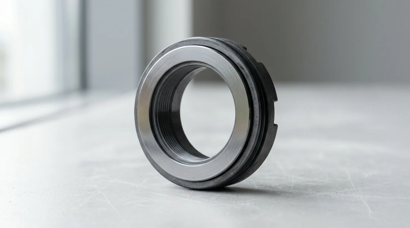
Why Thermal Cracking Matters in High-Temperature Pumps
In high-temperature centrifugal pumps, the mechanical seal face is the most critical dynamic boundary between the process fluid and the atmosphere. When exposed to extreme thermal stresses, these highly engineered surfaces become susceptible to thermal cracking, commonly known in the industry as “heat checking.” This phenomenon occurs when localized thermal expansion exceeds the material’s elastic limit, creating a network of micro-fractures across the sealing interface.
High-temperature applications typically involve process fluids exceeding 200°C (392°F), though thermal transients as low as 50°C per minute can induce enough thermal shock to initiate cracking in susceptible materials. Because seal faces rely on a microscopic fluid film for lubrication and cooling, any disruption in this film at elevated temperatures immediately causes boundary lubrication. The subsequent spike in frictional heat generates severe thermal gradients, making an understanding of thermal cracking essential for maintaining pump reliability in heavy industrial sectors.
Common Applications at Risk
Thermal cracking disproportionately affects continuous-process industries where high-temperature pumping is unavoidable. Boiler feed pumps in power generation facilities frequently handle water between 150°C and 250°C. Because water near its boiling point possesses poor lubricity and a low vapor pressure margin, these seals are highly vulnerable to localized flashing and subsequent thermal shock.
In the petrochemical and refining sectors, bottoms pumps, hot oil pumps, and heat transfer fluid (HTF) systems operating under API 682 Category 2 and Category 3 classifications face high risks. HTF systems routinely operate at temperatures reaching 350°C to 400°C. In these environments, any loss of cooling to the stuffing box or interruption in the external flush plan rapidly degrades the lubricating film, exposing the seal faces to extreme frictional heating and rapid thermal degradation.
Impact on Leakage, Reliability, and Safety
The onset of thermal cracking fundamentally compromises the integrity of the mechanical seal, leading to escalating leakage rates. A healthy mechanical seal in a high-temperature application typically exhibits unnoticeable fugitive emissions, often maintained well below the stringent Environmental Protection Agency (EPA) threshold of 500 parts per million (ppm) for volatile organic compounds (VOCs). When heat checking occurs, micro-fractures act as miniature pump grooves, dragging fluid across the seal face and accelerating leakage to visible, hazardous levels.
Beyond leakage, thermal cracking drastically reduces the Mean Time Between Failure (MTBF) of rotating equipment. A properly designed and supported high-temperature seal should achieve an MTBF of 36 to 48 months. However, recurrent thermal cracking can reduce this lifespan to less than three months, driving up maintenance costs and causing unplanned outages. Furthermore, in services handling auto-igniting fluids or highly toxic chemicals above their flash points, the sudden catastrophic failure of a thermally cracked seal poses severe fire, explosion, and personnel safety risks.
What Mechanical Seal Face Thermal Cracking Is
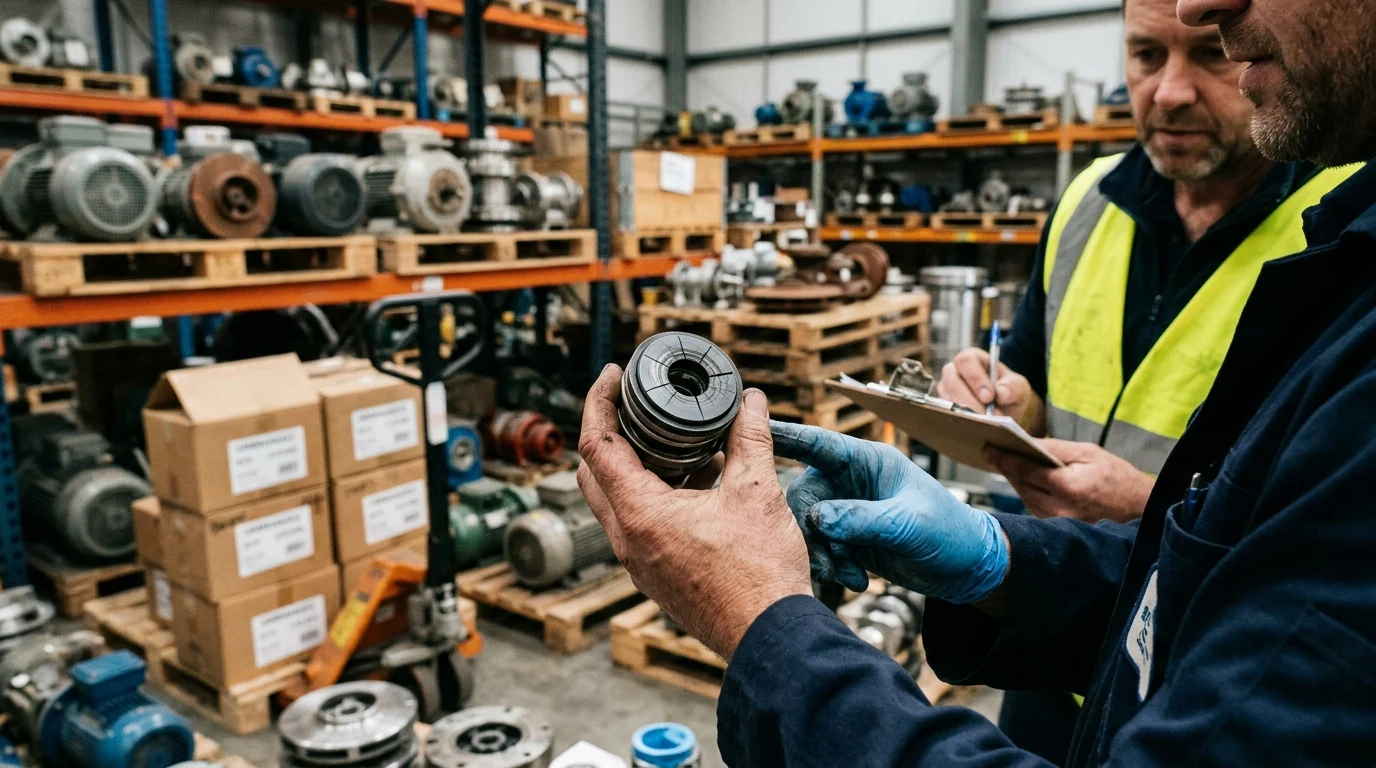
Mechanical seal face thermal cracking is a localized mechanical failure driven by extreme temperature gradients. During operation, the rubbing faces of a mechanical seal generate frictional heat. If the fluid film vaporizes or the cooling system fails, the temperature at the mating surface spikes instantaneously. The surface material attempts to expand, but the cooler substrate beneath restricts this expansion.
This differential expansion places the surface under immense compressive stress. When the pump stops, or if a cooler fluid suddenly re-enters the seal chamber, the surface cools and contracts rapidly. The previously compressed surface goes into severe tension, exceeding the ultimate tensile strength of the material. This cyclical thermal fatigue results in radial cracks. Metallurgical cross-sections typically reveal that these micro-cracks penetrate between 0.1 mm and 0.5 mm into the seal face, permanently altering the topography and destroying the required flatness.
Key Crack Patterns and Wear Signs
The physical manifestation of thermal cracking varies depending on the severity of the thermal shock and the specific materials involved. The most prevalent pattern is radial heat checking, characterized by fine cracks radiating outward from the center of the seal ring. In advanced stages, these cracks intersect, causing small fragments of the seal face material to spall or chip away, leaving behind a heavily pitted surface.
Another distinct pattern is the “comet tail,” which occurs when a localized hot spot or a hard particle embedded in the softer seal face scores the harder mating ring, creating a concentrated track of thermal damage. Blistering is also common in carbon-graphite faces, where subsurface hydrocarbons expand under extreme heat, causing raised bumps that eventually rupture.
| Crack Pattern | Primary Indicator | Root Cause Mechanism |
|---|---|---|
| Radial Heat Checking | Fine lines spanning from inner to outer diameter | Rapid heating followed by sudden quenching (thermal shock) |
| Comet Tails | Deep localized groove with trailing micro-cracks | Embedded particulate causing severe localized friction |
| Carbon Blistering | Raised, cracked bumps on carbon faces | Subsurface fluid expansion exceeding material porosity limits |
| Concentric Grooving | Deep circular wear tracks | Sustained dry running without immediate thermal fracture |
Leakage and Performance Symptoms
The earliest symptom of thermal cracking is often a subtle shift in the performance of the seal support system. Operators may notice erratic barrier fluid consumption in dual-seal configurations or minor pressure fluctuations within the stuffing box. As the cracks propagate and disrupt the 0.5- to 2.0-micron fluid film, the seal begins to exhibit weeping, which quickly escalates.
Performance degradation becomes measurable when leakage rates exceed the acceptable industry baseline of 5 to 10 mL/hour for liquid seals. A thermally cracked seal will frequently demonstrate leakage rates exceeding 50 mL/hour, accompanied by excessive vapor generation if the fluid is near its boiling point. Additionally, acoustic monitoring or vibration analysis of the pump housing may detect high-frequency squealing or chatter—a direct acoustic signature of the seal faces operating in a boundary lubrication regime due to a fractured, uneven surface topography.
Operating Conditions That Cause Thermal Cracking
The dynamic operating conditions within the pump’s stuffing box dictate the health of the mechanical seal. The fundamental requirement for preventing thermal cracking is maintaining a stable, microscopic fluid film between the primary seal faces. This film, typically measuring between 0.5 and 2.0 microns in thickness, physically separates the faces, reducing the coefficient of friction from approximately 0.30 (dry contact) to less than 0.05.
When operating conditions deviate from design parameters, this fluid film breaks down. The resulting dry or semi-dry contact generates immediate, intense frictional heat. Because the thermal mass of the seal faces is relatively small compared to the energy generated, surface temperatures can exceed 300°C above the bulk fluid temperature within seconds, setting the stage for catastrophic thermal fatigue.
Thermal Shock, Dry Running, and Vaporization
Thermal shock is the most direct cause of heat checking and is intimately linked to dry running and fluid vaporization. Flashing occurs when the pressure of the fluid between the seal faces drops below its vapor pressure due to the localized heat of friction. To prevent this, API 682 guidelines recommend maintaining a vapor pressure margin of at least 50 psi (3.4 bar) or a temperature margin of 20°C (36°F) above the fluid’s boiling point at the seal chamber pressure.
If this margin is lost, the liquid film vaporizes instantly. The seal faces lose their cooling and lubrication medium, leading to dry running. The subsequent temperature spike causes the faces to expand and distort. If the vapor bubble eventually collapses and cooler liquid rushes back onto the superheated seal face, the rapid quenching effect triggers the tensile stresses that fracture the material.
Startups, Shutdowns, Deadheading, and Cavitation
Transient pump conditions are highly detrimental to mechanical seal longevity. During startups, pumps often experience momentary dry running if the seal chamber has not been adequately vented. Entrapped air or process gas prevents the liquid from reaching the seal faces, resulting in immediate frictional heating before the process fluid can establish a lubricating film.
Deadheading—operating the pump with a closed discharge valve—is a severe operational error. Without flow to dissipate the heat generated by the impeller, the fluid inside the casing and stuffing box absorbs the mechanical energy. In high-energy pumps, deadheading can boil the process fluid within 60 to 120 seconds. Cavitation, caused by inadequate Net Positive Suction Head available (NPSHa), induces severe vibration and pressure pulsations. These pulsations can physically force the seal faces apart, allowing vapor to enter the gap and initiate thermal degradation.
Fluid Properties, Solids, Viscosity, and Lubrication Loss
The inherent properties of the process fluid heavily influence the risk of thermal cracking. Fluids with low viscosity and poor lubricity, such as hot water, liquid ammonia, and light hydrocarbons, struggle to maintain a robust fluid film under high load. When pumping these fluids, the margin for error regarding temperature and pressure control is exceptionally narrow.
The presence of abrasive solids further compounds the thermal risk. Suspended particulates can migrate into the seal interface, grinding against the faces and creating localized friction spikes. Furthermore, high-temperature operations can cause certain fluids to undergo polymerization or coking. If a fluid cokes at 250°C, the resulting hard carbon deposits can build up around the seal faces, restricting their axial movement. This “hang-up” prevents the faces from tracking each other properly, leading to uneven contact, localized dry running, and subsequent thermal cracking.
Material, Design, and Support System Factors
Engineering a mechanical seal to resist thermal cracking requires careful orchestration of material science, hydraulic design, and external support systems. The selection of materials is driven by their thermal conductivity, which dictates how fast heat is pulled away from the rubbing faces, and their coefficient of thermal expansion (CTE), which dictates how much the material distorts under heat.
In high-temperature applications, standard carbon-ceramic pairings are entirely inadequate. Instead, engineers must rely on advanced engineered ceramics and specialized carbon grades. Furthermore, the physical geometry of the seal faces and the implementation of robust API flush plans are critical to maintaining the thermal equilibrium of the stuffing box.
Seal Face Material Pairings
The choice of seal face material pairing is the primary defense against heat checking. Hard-on-hard pairings, such as Silicon Carbide (SiC) against Tungsten Carbide (TC), are common in abrasive high-temperature applications. Sintered Alpha Silicon Carbide (SSiC) offers excellent chemical resistance and high thermal conductivity (~120 W/m·K), while Tungsten Carbide provides high fracture toughness but lower thermal conductivity (~80 W/m·K).
For applications prone to marginal lubrication, a hard-on-soft pairing is preferred. Premium antimony-impregnated carbon graphite paired with SiC provides excellent dry-running survivability. The antimony impregnation enhances the carbon’s structural integrity and thermal conductivity at temperatures up to 350°C. Reaction Bonded Silicon Carbide (RBSiC) is also utilized for its free graphite content, which acts as a solid lubricant during transient dry-running events.
| Material Pairing | Thermal Conductivity (W/m·K) | Max Temp Limit (°C) | Thermal Shock Resistance | Best Application Fit |
|---|---|---|---|---|
| SSiC vs. Antimony Carbon | 120 / 25 | 350 | Excellent | Boiler feed, hot hydrocarbons |
| SSiC vs. SSiC | 120 / 120 | 400+ | Moderate | Highly corrosive, abrasive hot fluids |
| SSiC vs. Tungsten Carbide | 120 / 80 | 400 | Good | High-pressure abrasive slurries |
| Alumina vs. Resin Carbon | 30 / 15 | 200 | Poor | Light chemical, low temp water |
Flush Plans, Barrier Fluids, and Cooling Systems
Mechanical seals in high-temperature service cannot survive without an external support system. API 682 piping plans are designed to modify the environment of the stuffing box. Plan 21 and Plan 23 involve cooling the process fluid. Plan 23 is highly efficient for boiler feed pumps, circulating fluid solely from the stuffing box through a heat exchanger and back. It typically requires a cooling water flow of 2 to 4 gallons per minute (GPM) to maintain the seal chamber 50°C below the pump’s bulk temperature.
For highly hazardous or extremely hot fluids, dual seals with barrier fluids are deployed. API Plan 53B (pressurized bladder accumulator) or Plan 54 (external pressurized lubrication system) utilize synthetic thermal oils to provide a clean, cool, and highly lubricious fluid film between the inner and outer seal faces, completely isolating them from the high-temperature process fluid.
Key Design Trade-Offs
Design engineers must balance hydraulic closing forces to prevent thermal overload. The balance ratio of a mechanical seal—the ratio of the hydraulic closing area to the seal face opening area—is typically engineered between 0.75 and 0.85 for high-pressure, high-temperature applications. A lower balance ratio reduces the closing force and frictional heat but increases the risk of the faces blowing open during pressure spikes.
Face geometry also plays a pivotal role. Narrow seal faces generate less heat but wear faster. To improve fluid film generation in challenging high-temperature fluids, engineers may incorporate hydropads or laser-machined Rayleigh steps onto the seal face. These micro-features generate hydrodynamic lift, forcing fluid between the faces to cool them. The trade-off is a slight, calculated increase in the baseline leakage rate, which is often an acceptable compromise to eliminate the risk of catastrophic thermal cracking.
How to Diagnose, Prevent, and Correct Thermal Cracking
Successfully mitigating thermal cracking requires a shift from reactive replacement to proactive root cause analysis. Industry data indicates that nearly 70% of mechanical seal failures are driven by operational or system-level issues rather than inherent flaws in the seal design itself. Therefore, simply replacing a cracked seal with an identical unit almost guarantees a repeat failure.
Diagnosing the precise mechanism of thermal failure demands rigorous inspection protocols during the pump teardown, followed by targeted corrective actions that address the thermodynamic and hydraulic realities of the pumping system.
Inspection and Root Cause Analysis Steps
The diagnostic process begins the moment the failed seal is extracted. Visual inspection under magnification is required to identify the specific crack morphology. Radial cracks indicate rapid thermal shock, while deep concentric grooving points to sustained dry running under high load. Engineers utilize optical flats and monochromatic light sources to measure the distortion of the seal face.
Surface flatness is measured in helium light bands, where one light band equals 11.6 microinches (0.29 microns). A thermally distorted face will show highly irregular, intersecting light bands rather than the parallel lines indicative of a flat surface. In complex failure investigations, Scanning Electron Microscopy (SEM) and Energy Dispersive X-Ray Spectroscopy (EDX) may be employed to detect microscopic material transfer between the faces, confirming whether boundary lubrication and localized welding preceded the thermal fracture.
Corrective Actions to Prevent Repeat Failures
Once the root cause is established, corrective actions must focus on restoring and maintaining the fluid film. If vaporization is the culprit, operators must increase the seal chamber pressure by enlarging the flush throat bushing or upgrading the cooling capacity of the API 23 heat exchanger. Implementing automated venting procedures ensures that entrained gases are purged before startup, eliminating initial dry running.
To combat deadheading and transient thermal shocks, facilities should integrate Variable Frequency Drives (VFDs) and minimum flow bypass lines. A minimum flow bypass guarantees that even if the primary discharge valve is closed, a baseline flow rate (often 15% to 25% of the Best Efficiency Point flow) continually circulates through the pump, dissipating the heat generated by the impeller and protecting the stuffing box from rapid temperature spikes.
Material Selection and Final Decision Guide
When system upgrades are physically or economically unfeasible, upgrading the seal face material is the final corrective lever. For applications plagued by unavoidable, intermittent dry running, migrating from standard SSiC to specialized diamond-coated Silicon Carbide provides an extreme level of protection. Diamond coatings reduce the dry-running coefficient of friction to below 0.02, allowing the seal to survive loss-of-lubrication events with negligible heat generation.
Ultimately, the decision to upgrade materials or redesign the support system must be guided by lifecycle cost analysis. While advanced materials like diamond-coated SiC or complex API 54 barrier systems require a higher initial capital expenditure (CapEx), their ability to extend MTBF from a few months to over four years drastically reduces operational expenditure (OpEx). This effectively eliminates the costly downtime and environmental hazards associated with mechanical seal face thermal cracking.
Key Takeaways
- Treat pump services above 200°C (392°F) as high-risk for mechanical seal face thermal cracking and verify face material, flush plan, and cooling capacity before operation.
- Avoid rapid temperature changes because thermal transients around 50°C per minute can initiate cracking in vulnerable seal face materials.
- Maintain a stable lubricating film across the seal faces, since film collapse leads to boundary lubrication, frictional heat spikes, and heat checking.
- Pay special attention to boiler feed, hot oil, refinery bottoms, and heat transfer fluid pumps because these services combine high temperature with low lubricity or flashing risk.
- Investigate recurring seal failures quickly, as thermal cracking can reduce expected seal life from 36–48 months to less than three months.
- Use the correct seal face material pairing and support system to reduce leakage, protect personnel, and improve pump reliability in high-temperature service.
Frequently Asked Questions
What is thermal cracking on a mechanical seal face?
Thermal cracking, or heat checking, is a network of micro-fractures caused by steep temperature gradients across the seal face. It often starts when the lubricating film breaks down and frictional heat rises faster than the face material can absorb or dissipate.
At what temperatures do high-temperature pump seals become vulnerable?
Applications above 200°C (392°F) are commonly considered high risk, but rapid thermal transients as low as 50°C per minute can also trigger cracking, especially when cooling, flush flow, or lubrication is unstable.
Which pump applications are most at risk of seal face heat checking?
Boiler feed pumps, hot oil pumps, refinery bottoms pumps, and heat transfer fluid systems are high-risk services. These applications often combine high temperature, poor lubricity, flashing risk, and severe thermal cycling.
How does thermal cracking increase mechanical seal leakage?
Micro-cracks act like tiny pumping grooves across the seal face. They disrupt the sealing interface, pull fluid through the contact zone, and can turn normally minimal emissions into visible or hazardous leakage.
Can material selection reduce seal face thermal cracking?
Yes. Choosing seal face materials with suitable thermal conductivity, strength, and shock resistance is critical. The correct carbon, silicon carbide, or tungsten carbide pairing depends on temperature, fluid properties, pressure, speed, and flush plan.

Post time: Jul-29-2026