


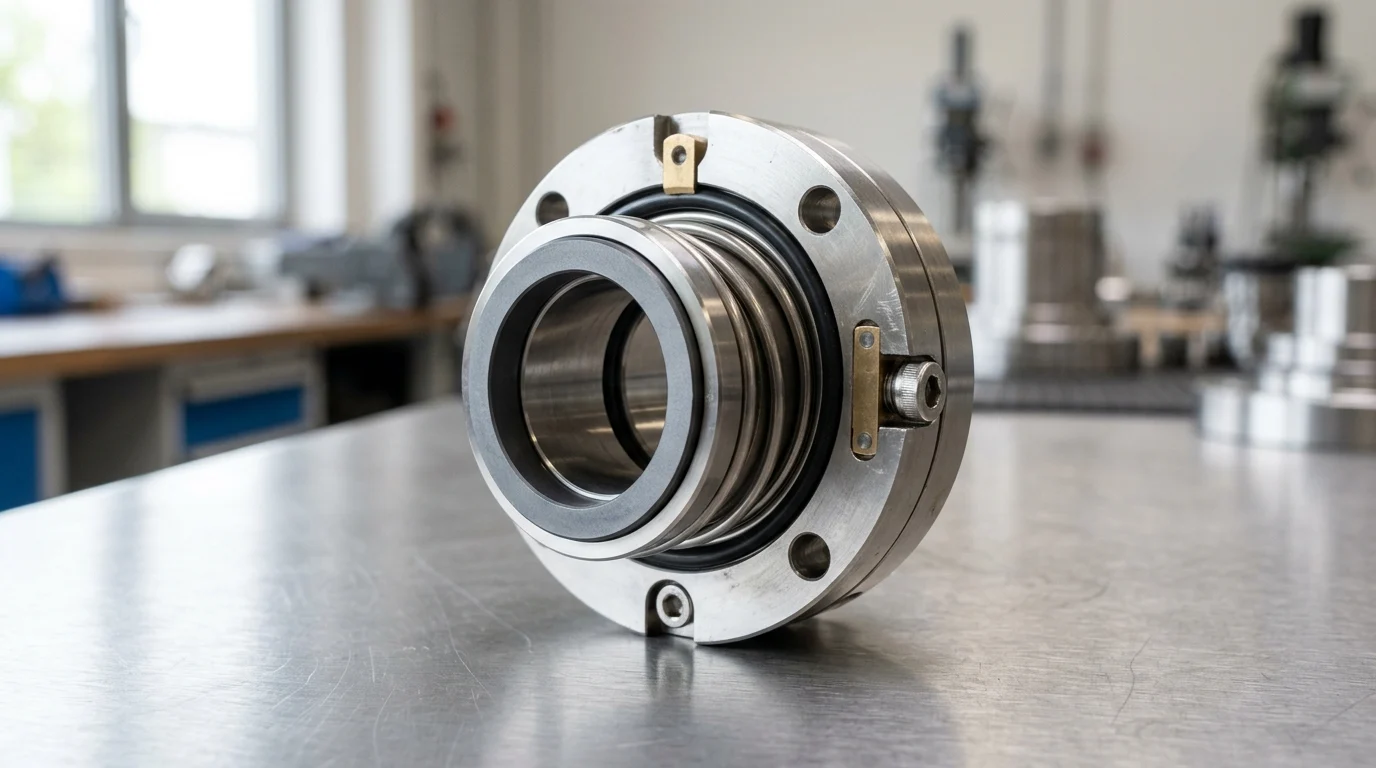
Why Mechanical Seal Selection Is Strategic
In chemical processing environments, the mechanical seal represents the critical boundary between hazardous process fluids and the atmosphere. Selecting the correct sealing technology is not merely a routine maintenance decision; it is a foundational component of plant engineering that dictates operational uptime, environmental compliance, and overall safety. While modern centrifugal pumps are engineered for decades of service, the mechanical seal remains a highly sensitive wear component, frequently acting as the primary limiting factor for a pump’s Mean Time Between Failures (MTBF).
A strategic approach to seal selection shifts the focus from initial procurement cost to Total Cost of Ownership (TCO) and long-term reliability. By analyzing the tribological interactions at the seal faces and the specific thermodynamic conditions of the process, plant engineers can systematically elevate average pump MTBF from a baseline of 12 to 18 months to a highly optimized 48 to 60 months. This transformation requires treating the mechanical seal not as a standalone commodity, but as an integral part of a complex fluid handling system.
How Seals Affect Pump Reliability and Emissions
The correlation between mechanical seal design and centrifugal pump reliability is direct and significant. An improperly specified seal will suffer from premature face degradation, thermal distortion, or elastomer extrusion, drastically reducing pump availability and causing cascading mechanical issues such as bearing contamination. When the fluid film between the seal faces breaks down due to incorrect specification, the resulting friction generates extreme heat, leading to thermal cracking and catastrophic failure.
Furthermore, chemical processors face increasingly stringent environmental regulations regarding volatile organic compound (VOC) and hazardous air pollutant (HAP) emissions. Regulatory bodies such as the EPA, under the Clean Air Act, mandate strict fugitive emission thresholds. These regulations often require mechanical seals to limit leakage rates to below 500 parts per million (ppm), with some localized regulations and specific hazardous chemicals enforcing limits as severe as 100 ppm or even 50 ppm. Achieving these ultra-low emission targets requires highly engineered seal geometries, optimal face loading, and often, the implementation of dual unpressurized or pressurized sealing arrangements.
Failure Costs Beyond the Seal Itself
The financial impact of a seal failure extends significantly beyond the procurement cost of the replacement component itself. In continuous-process petrochemical and chemical manufacturing facilities, unpredicted downtime is heavily penalized. Depending on the scale of the operation, an unplanned pump outage can incur financial penalties ranging from $10,000 to over $50,000 per hour in lost production yield and process interruption.
Additionally, hazardous fluid containment breaches necessitate costly environmental remediation, specialized hazardous material handling, and potential regulatory fines. When accounting for emergency maintenance labor, decontamination procedures, replacement of secondary damaged components (like bearings and shafts), and lost product, the total cost of a catastrophic mechanical seal failure routinely exceeds the initial capital expenditure of the entire pump system by a factor of ten. Therefore, investing in advanced sealing technology and rigorous selection protocols is a high-return risk mitigation strategy.
Key Mechanical Seal Types and Configurations
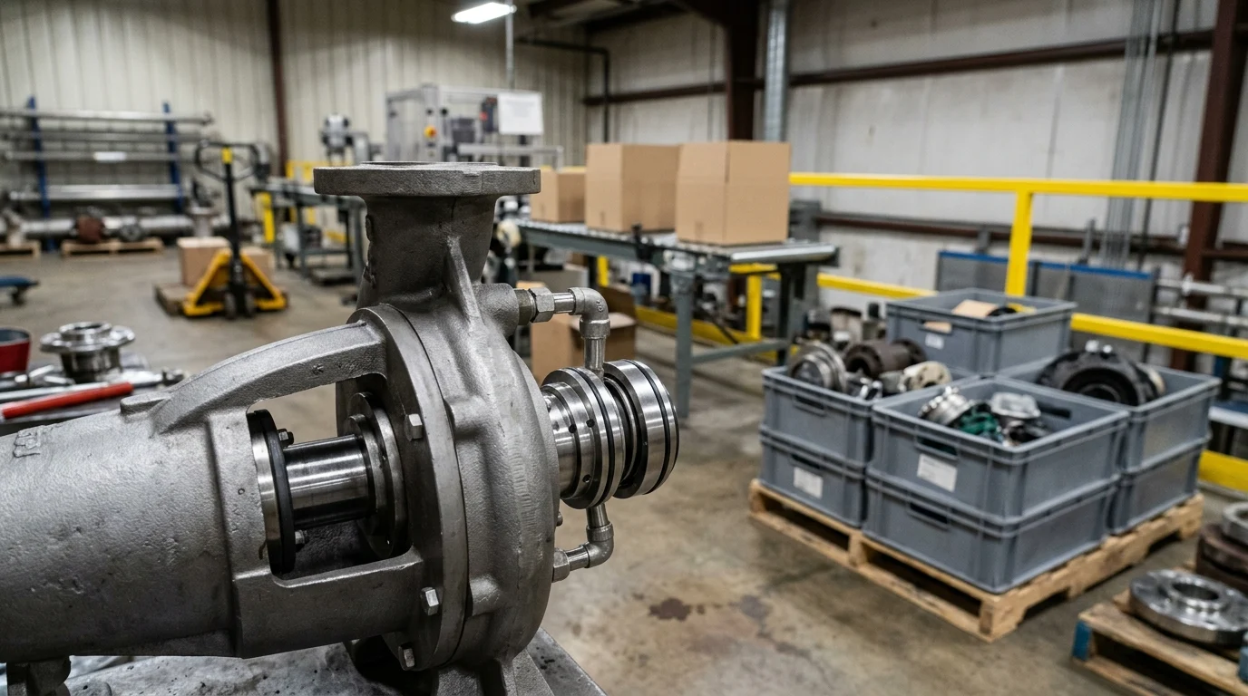
Mechanical seal architectures vary significantly to accommodate diverse fluid properties, spatial constraints within the pump stuffing box, and specific operational philosophies. The core configuration dictates not only the seal’s tolerance to pressure, temperature, and chemical attack but also the complexity of its installation and subsequent maintenance procedures. Understanding these primary design classifications is the first step in narrowing down the appropriate technology for a given chemical application.
Component Seals vs Cartridge Seals
Historically, component seals were the industry standard, requiring highly skilled technicians to manually assemble individual springs, secondary O-rings, and precision seal faces directly onto the pump shaft. This method demands exact measurement to set the correct working length and spring compression. Even minor miscalculations can lead to uneven face loading, excessive heat generation, or immediate leakage upon startup.
Conversely, cartridge seals are pre-assembled and pre-set at the factory, housing the rotating element, stationary face, gland plate, and sleeve in a single, unitized assembly. Industry reliability data indicates that up to 30% of component seal failures in chemical plants are directly attributable to installation errors. By transitioning to cartridge seals, facilities effectively eliminate setting-dimension errors, significantly reducing installation time from several hours to under an hour, and drastically improving initial startup reliability. While the initial capital cost of a cartridge seal is higher, the reduction in maintenance labor and downtime makes it the preferred choice for modern chemical processing.
| Feature | Cartridge Seals | Component Seals |
|---|---|---|
| Installation Complexity | Low (Pre-set at factory) | High (Requires precise measurement) |
| Installation Error Rate | < 5% | ~ 30% |
| Initial Capital Cost | Higher (Typically 1.5x to 2x) | Lower |
| Maintenance Downtime | 1 to 2 hours | 4 to 8 hours |
| Ideal Application | Standard chemical processing, API pumps | Space-constrained or legacy non-standard pumps |
Balanced, Unbalanced, Pusher, and Non-Pusher Seals
The balance ratio of a mechanical seal determines its ability to withstand hydraulic forces and manage heat generation. Unbalanced seals allow the full hydraulic pressure of the stuffing box to act on the back of the seal face, forcing it against the stationary face. This limits their application to lower pressures, typically below 150 psig (10 bar), as higher pressures will squeeze out the lubricating fluid film, causing dry running and rapid wear. Balanced seals feature a mathematically calculated stepped shaft or sleeve design that reduces the hydraulic closing force area. This enables operation at pressures exceeding 400 psig (27 bar) while maintaining a stable fluid film and minimizing heat generation.
Furthermore, the choice between pusher and non-pusher configurations is critical for chemical compatibility and thermal stability. Pusher seals utilize a dynamic secondary O-ring that must move axially along the shaft to compensate for minute face wear and shaft movement. In corrosive or crystallizing chemical applications, this can lead to shaft fretting or O-ring hang-up, causing the seal faces to open. Non-pusher seals, utilizing edge-welded metal bellows, eliminate the dynamic O-ring entirely. The bellows act as both the spring mechanism and the secondary seal, making them exceptionally suited for high-temperature applications up to 400°C (750°F) or fluids containing crystallizing compounds that would normally jam a pusher seal.
Seal Faces, Elastomers, and Hardware Materials
Material selection for seal faces, elastomers, and metallurgy defines the chemical resistance and thermal limits of the assembly. Primary face materials typically involve a combination of Silicon Carbide (SiC), Tungsten Carbide (TC), or specialized resin-impregnated Carbon. Silicon Carbide offers exceptional hardness, chemical inertness, and thermal conductivity, making it the default choice for abrasive chemical applications. Carbon is often used as a mating face due to its self-lubricating properties, which provide a safety margin during temporary dry-running conditions.
Elastomers, which form the secondary sealing elements (O-rings and gaskets), must be meticulously matched to the process fluid. Standard Fluoroelastomers (FKM, e.g., Viton) handle many general chemicals up to 200°C (392°F). However, aggressive solvents, strong caustics, or amines necessitate Perfluoroelastomers (FFKM, e.g., Kalrez), which offer near-universal chemical resistance and temperature tolerance up to 320°C (608°F), albeit at a significantly higher cost. Hardware materials (glands, sleeves, and springs) typically default to 316 Stainless Steel, but highly corrosive environments like hydrochloric or sulfuric acid processing require advanced alloys such as Alloy C-276 (Hastelloy), Alloy 20, or Titanium to prevent rapid metallurgical degradation.
Process Conditions That Drive Seal Selection
The operational environment inside the seal chamber dictates the required mechanical seal geometry, face treatments, and material composition. Process conditions must be analyzed meticulously, as even minor fluctuations in fluid dynamics, thermal states, or mechanical stability can instantaneously compromise the nanometer-thick fluid film necessary for seal face lubrication. A comprehensive understanding of the pumped media’s physical and chemical state is non-negotiable for successful seal specification.
Fluid Chemistry, Solids, and Vapor Pressure
The chemical composition and pH of the pumped media determine baseline material compatibility, but physical properties like solids concentration, viscosity, and vapor pressure drive the mechanical and tribological design. Fluids with suspended solids exceeding 5% to 10% by weight typically require hard-on-hard face combinations (e.g., Silicon Carbide against Silicon Carbide) to prevent rapid abrasive wear that would quickly destroy a softer Carbon face. High-viscosity fluids (exceeding 3,000 cSt) require robust drive mechanisms and heavy-duty springs to prevent torsional shearing of the seal components.
Vapor pressure is arguably the most critical thermodynamic parameter. The process fluid must remain in a stable liquid state between the seal faces to provide hydrodynamic lubrication and cooling. A standard engineering rule dictates maintaining a seal chamber pressure of at least 50 psi (3.4 bar), or a minimum 10% pressure margin, above the fluid’s vapor pressure at the maximum operating temperature. Failure to maintain this margin results in flashing—where the fluid instantly vaporizes across the pressure drop of the seal faces. Flashing causes violent face popping, loss of lubrication, severe thermal shock, and immediate, catastrophic seal failure.
Temperature, Pressure, Speed, and Shaft Movement
Operational kinematics—specifically temperature, pressure, rotational speed, and shaft stability—must fall strictly within the mechanical seal’s engineered limits. High-speed centrifugal pumps generate significant centrifugal forces and friction-induced heat at the seal faces. Applications involving high shaft speeds (e.g., exceeding 3,600 RPM) or high pressures require advanced face topographies, such as laser-machined hydrodynamic grooves, to actively pump fluid between the faces and maintain cooling.
Furthermore, mechanical seals have exceptionally strict tolerances for shaft movement and alignment. To ensure reliable operation and prevent premature fatigue of flexible elements, radial shaft deflection must typically be maintained below 0.002 inches (0.05 mm) Total Indicator Reading (TIR) at the seal faces. Axial end-play should not exceed 0.005 inches (0.13 mm). Excessive pump vibration, cavitation, or pipe strain leading to misalignment will rapidly fatigue metal bellows, cause pusher seal O-rings to fret the pump sleeve, and ultimately shatter brittle Silicon Carbide seal faces.
Mechanical Seal Material Comparison
Comparing material combinations is essential for balancing operational longevity with procurement cost. The Pressure-Velocity (PV) limit is a standard engineering metric used to evaluate a face material combination’s capacity to handle the heat generated by the system’s pressure and the shaft’s rotational speed. Exceeding a material’s PV limit results in thermal cracking, heat checking, or blistering of the seal faces.
| Face Material Combination | Typical PV Limit (psi-ft/min) | Friction Coefficient | Common Chemical Applications |
|---|---|---|---|
| Carbon vs. Ceramic | 100,000 | 0.04 – 0.07 | Water, light non-hazardous chemicals, low pressure |
| Carbon vs. Silicon Carbide | 500,000 | 0.02 – 0.05 | General hydrocarbons, low-abrasion acids, moderate speed |
| Silicon Carbide vs. Silicon Carbide | 800,000 | 0.08 – 0.15 | Highly abrasive slurries, strong caustics, high pressure |
| Tungsten Carbide vs. Silicon Carbide | 700,000 | 0.07 – 0.12 | High-impact applications, heavy sludge, extreme torque |
While Carbon against Silicon Carbide provides an excellent balance of high PV limits and low friction for general chemical duties, the introduction of abrasives necessitates the transition to Silicon Carbide against Silicon Carbide. Although this hard-on-hard combination withstands abrasion, its higher friction coefficient generates more heat, thereby demanding stricter adherence to cooling and flush plans to prevent thermal failure.
Seal Support Systems and Standards
Even the most robustly engineered mechanical seal will fail prematurely if forced to operate in an inadequate or uncontrolled environment. Seal support systems are specialized fluid management circuits designed to control the micro-environment around the seal faces, actively regulating temperature, pressure, and fluid cleanliness. The American Petroleum Institute (API) Standard 682 is the globally recognized, definitive framework guiding the design, testing, and implementation of these systems in the chemical, petrochemical, and refining sectors.
API 682 Categories, Arrangements, and Seal Plans
API 682 categorizes mechanical seals based on pump shaft size, operational severity, and testing requirements. Category 1 seals are designed for general purpose, non-API 610 pumps with shaft sizes ranging from 20 mm to 110 mm, handling temperatures up to 260°C (500°F). Categories 2 and 3 apply specifically to heavy-duty API 610 pumps, with Category 3 requiring the most stringent design documentation, qualification testing, and material traceability for critical refinery applications.
Beyond categories, API 682 defines the physical seal Arrangements. Arrangement 1 designates a single mechanical seal, suitable for safe, non-volatile fluids. Arrangement 2 specifies an unpressurized dual seal setup, providing a secondary backup seal and a method to capture minor leakage. Arrangement 3 indicates a pressurized dual seal configuration, where a barrier fluid is maintained at a higher pressure than the process fluid, ensuring absolute zero emissions of the pumped media to the atmosphere. Selecting the correct Arrangement is the foundational step in aligning the mechanical seal with the required environmental piping plan.
Barrier Fluid, Buffer Fluid, Flush, and Quench Systems
API Piping plans dictate exactly how fluids are routed to and from the seal chamber to maintain stable operation. A simple flush system (e.g., API Plan 11) routes fluid from the pump’s discharge, through an orifice, and directly into the seal chamber to provide cooling, lubrication, and to sweep away vapor bubbles. In dual seal configurations, specialized barrier and buffer fluids are introduced via dedicated reservoirs and heat exchangers.
A buffer fluid system (API Plan 52) operates in an unpressurized state—typically maintained at 15 to 30 psig below the seal chamber pressure. This ensures that any inner seal leakage is safely captured in the buffer reservoir rather than escaping to the atmosphere. Conversely, a barrier fluid system (API Plan 53A, 53B, or 53C) is artificially pressurized at least 15 to 30 psig above the maximum seal chamber pressure. This guarantees that if the inner seal face breaches, the clean, benign barrier fluid leaks inward into the process, absolutely preventing hazardous process fluid from escaping outward. Quench systems (API Plan 62) use low-pressure steam, water, or nitrogen on the atmospheric side of the seal to prevent the crystallization or coking of product leakage, which would otherwise physically lock the seal faces.
Environmental and Safety Requirements
Environmental regulations and occupational safety mandates heavily influence the selection of seal support systems. For fluids categorized as lethal, highly toxic, carcinogenic, or highly flammable—such as hydrogen sulfide (H2S), benzene, hydrofluoric acid, or concentrated sulfuric acid—regulatory standards universally require Arrangement 3 (pressurized dual seals). This configuration provides a zero-emissions guarantee during normal operation, protecting both plant personnel and the surrounding environment.
To comply with safety standards, the support system must also include sophisticated instrumentation. Pressurized barrier reservoirs (Plan 53A) are typically equipped with pressure transmitters and level switches. These instruments are integrated into the plant’s Distributed Control System (DCS) to trigger immediate control room alarms if the barrier pressure drops below the process pressure, or if the fluid volume changes by more than 10%, indicating a critical seal breach. This automated monitoring is essential for safely shutting down the pump before a catastrophic release occurs.
How to Make the Final Seal Selection
Finalizing the selection of a mechanical seal requires a structured, multidisciplinary approach that bridges process engineering, maintenance reliability, and procurement. Plant engineers must synthesize fluid dynamics data, long-term reliability goals, and stringent regulatory requirements into a cohesive procurement specification. This specification must leave no room for ambiguity during the manufacturing, testing, and installation phases, ensuring the delivered seal performs exactly as modeled.
Step-by-Step Selection Process
The selection process follows a strict, sequential hierarchy to eliminate inappropriate technologies early in the evaluation. Step one involves defining the exact chemical composition, concentration percentage, and pH of the fluid to establish elastomer and metallurgy compatibility. Step two maps the complete operating envelope, documenting normal, maximum, and minimum temperatures and pressures to calculate required vapor pressure margins and verify PV limits.
Step three assesses the environmental and safety hazards to dictate the choice between a single seal (Arrangement 1) or a dual seal (Arrangements 2 or 3). Step four determines the necessary API piping plan to support the selected arrangement, factoring in the availability and cost of plant utilities like cooling water, instrument air, nitrogen, or clean barrier fluids. Finally, step five involves evaluating the physical space constraints of the pump’s stuffing box to ensure the selected cartridge assembly will fit without requiring extensive machining of the pump casing.
Using OEM and Seal Vendor Guidance
Collaborating intimately with Original Equipment Manufacturers (OEMs) and specialized seal vendors is critical for mitigating operational risk. Vendors utilize advanced proprietary software to perform finite element analysis (FEA), modeling face deformation, thermal gradients, and fluid film thickness under the plant’s specific operating conditions. Plant operators should actively demand historical MTBF data and case studies for proposed seal designs operating in identical or highly similar chemical applications.
A properly specified, installed, and operated API 682 mechanical seal in a clean chemical application should reliably achieve an MTBF of 36 to 60 months. Engaging vendors early in the design phase also allows for custom engineering solutions, such as modifying the seal gland to accommodate specific legacy pump bolting patterns, integrating specialized cooling jackets for high-temperature service, or selecting optimized barrier fluids that will not contaminate the process if an inner seal failure occurs.
Final Decision Criteria to Document
The final procurement decision must be backed by rigorous documentation to ensure traceability, quality control, and compliance with plant standards. Engineers should require standardized API 682 data sheets detailing all operating parameters, selected materials, and utility consumption rates. Material test reports, particularly EN 10204 3.1 certificates, must be strictly mandated for all pressure-retaining metallic components (glands, sleeves, and collars) to verify exact alloy composition and mechanical properties.
Furthermore, the final criteria should stipulate comprehensive factory acceptance testing (FAT). API 682 mandates hydrostatic testing of the seal gland assembly at 1.5 times the Maximum Allowable Working Pressure (MAWP) for a minimum of 30 minutes with zero visible leakage. For critical Category 3 applications, dynamic testing may also be required to verify rotational performance, heat generation, and leakage rates prior to shipment.
Key Takeaways
- Select mechanical seals by fluid chemistry, pressure, temperature, speed, solids content, and emission targets instead of relying only on initial purchase price.
- Treat the seal as a system component because an incorrect specification can reduce pump uptime through face damage, heat generation, elastomer failure, or bearing contamination.
- Use dual seal arrangements for hazardous, volatile, or highly regulated chemicals to help meet fugitive emission limits that may fall below 500 ppm, 100 ppm, or even 50 ppm.
- Evaluate total cost of ownership because an unplanned chemical pump outage can cost $10,000 to more than $50,000 per hour in lost production.
- Optimize seal design, materials, and support systems to improve pump MTBF from a typical 12–18 months toward 48–60 months in demanding services.
- Consider cartridge, double, elastomer bellow, wave spring, and OEM replacement designs according to installation requirements, maintenance capability, and process risk.
Frequently Asked Questions
How do I choose the right mechanical seal for a chemical processing pump?
Start with the fluid chemistry, temperature, pressure, solids content, shaft speed, and emission limits. Then match the seal arrangement, face materials, elastomers, and flush plan to those conditions rather than selecting by pump size alone.
When should I use a double mechanical seal?
Use a double seal when the fluid is hazardous, toxic, volatile, abrasive, or environmentally regulated. Pressurized or unpressurized dual arrangements help control leakage, protect seal faces, and support compliance with strict VOC or HAP emission limits.
Why do mechanical seals fail early in chemical pumps?
Common causes include chemical incompatibility, dry running, poor lubrication film, incorrect face loading, thermal distortion, abrasive solids, vibration, and wrong elastomer selection. Many failures are specification or operating-condition problems, not just component defects.
What leakage level is acceptable for chemical pump seals?
Acceptable leakage depends on the chemical and regulation. Many facilities target below 500 ppm for fugitive emissions, while more hazardous services may require 100 ppm, 50 ppm, or tighter limits using advanced seal designs and monitoring.
How can better seal selection improve pump MTBF?
A properly selected seal can reduce face wear, heat generation, elastomer damage, and contamination. In optimized systems, pump MTBF may improve from 12–18 months to 48–60 months when seal design, materials, and operating support systems are aligned.

Post time: Aug-03-2026