


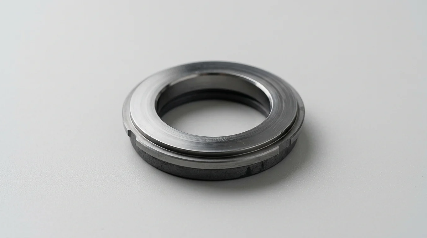
Why Mechanical Seal Face Cracking Is a Strategic Risk
In centrifugal pump and rotating equipment applications, the mechanical seal face functions as the primary dynamic barrier between the process fluid and the atmosphere. Maintaining the integrity of this interface is a fundamental requirement for plant reliability. Industry reliability data consistently demonstrates that mechanical seal failures account for 60% to 70% of all centrifugal pump maintenance events, with face damage being a leading mode of failure. Because the stationary and rotating faces operate with microscopic clearances, even minor structural degradation can compromise the fluid containment envelope.
Mechanical seal face cracking is rarely a spontaneous manufacturing defect; rather, it is a symptom of severe operational distress. When a seal face fractures, it signifies that the operational environment has exceeded the mechanical or thermal limits of the seal materials. Understanding the mechanics of this failure mode is essential for reliability engineers seeking to extend Mean Time Between Failures (MTBF) and reduce the total lifecycle costs of fluid handling systems.
What Seal Face Cracking Means
At the microscopic level, a mechanical seal operates in a state of boundary or mixed friction lubrication. The rotating and stationary faces are separated by an ultra-thin hydrodynamic fluid film, typically measuring between 0.25 and 3.0 microns in thickness. This film provides essential lubrication and cooling, preventing direct asperity contact between the two mating surfaces.
Seal face cracking occurs when this tribological balance is destroyed, subjecting the brittle face materials to extreme localized stresses. The cracking can manifest in several distinct morphologies, ranging from microscopic surface crazing to catastrophic transverse fractures. Because high-performance seal faces are typically manufactured from extremely hard but brittle ceramics or carbides, they possess high compressive strength but relatively low tensile strength. When tensile stresses—induced by rapid thermal expansion or severe mechanical deflection—exceed the material’s modulus of rupture, the face fractures.
How Cracks Cause Downtime, Leakage, and Safety Risks
The immediate consequence of a cracked seal face is the loss of the primary containment barrier, leading to process fluid leakage. Depending on the fluid’s properties, this leakage introduces severe safety and environmental hazards. In refining and petrochemical operations, the release of Volatile Organic Compounds (VOCs) can quickly exceed strict environmental compliance thresholds, such as the EPA Method 21 limit, which often mandates action if emissions surpass 500 parts per million by volume (ppmv).
Beyond regulatory penalties, the financial impact of seal face cracking is heavily weighted toward operational downtime. While a standard API 682 mechanical seal replacement might incur direct hardware costs ranging from $3,000 to $15,000, the associated production losses can easily exceed $50,000 per hour in high-throughput continuous processing facilities. Furthermore, sudden catastrophic face shattering can introduce abrasive ceramic particulate into the pump casing, potentially causing secondary damage to wear rings, impellers, and bearings, thereby extending the required repair scope.
Common Operating Causes of Seal Face Cracking
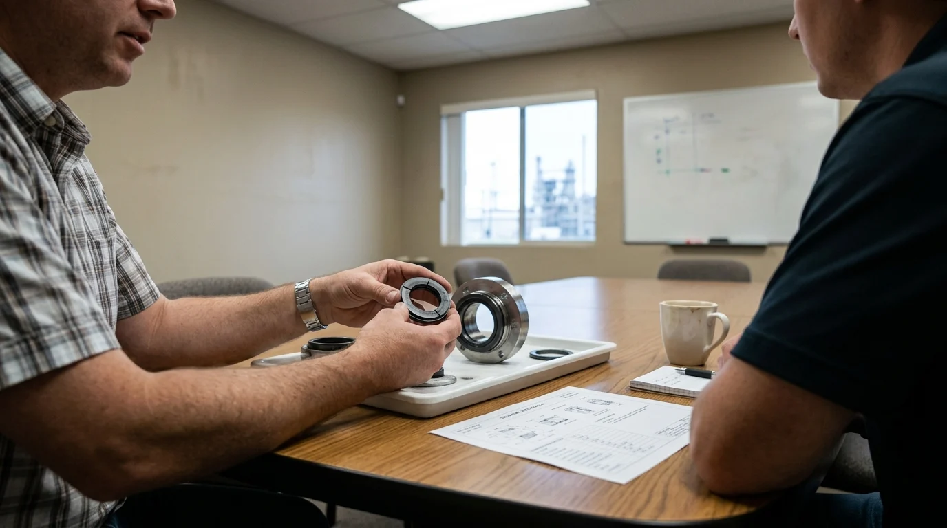
The longevity of a mechanical seal is dictated by the environment within the seal chamber. While mechanical seals are precision-engineered components, they are highly sensitive to adverse operating conditions that disrupt their required lubrication and cooling mechanisms.
Identifying the specific operating conditions that induce face cracking requires an understanding of fluid dynamics, thermodynamics, and mechanical force transmission within the pump. The vast majority of cracked faces result from three primary operational anomalies: inadequate lubrication, severe temperature fluctuations, and mechanical overload.
Dry Running and Poor Lubrication
Dry running is the most common precursor to seal face cracking. When the process fluid vaporizes or is evacuated from the seal chamber, the hydrodynamic film between the seal faces collapses. Without this lubricating film, the coefficient of friction at the interface spikes dramatically, often rising from a nominal 0.05 to over 0.30.
This sudden increase in friction generates immense localized heat. Under dry running conditions, the temperature at the seal interface can escalate at rates exceeding 100°C per minute. Because materials like silicon carbide and tungsten carbide have distinct thermal expansion coefficients, this rapid, localized heating causes the face material to expand unevenly. The resulting thermal gradients create massive internal tensile stresses that initiate micro-cracks across the running band, eventually propagating into deep structural fractures if the dry running condition persists.
Thermal Shock and Temperature Cycling
Thermal shock occurs when a seal face experiences an instantaneous and drastic change in temperature. This is most frequently observed when a pump that has been running dry or operating dead-headed (generating extreme heat) is suddenly flooded with a cold process fluid or flush fluid. For example, if a seal face operating at 250°C is abruptly quenched by a flush fluid entering at 30°C, the surface of the material contracts at a much faster rate than the underlying substrate.
This differential contraction induces severe tensile stress on the face surface. Brittle materials, particularly aluminum oxide ceramics and certain grades of silicon carbide, are highly susceptible to this phenomenon. The signature of thermal shock is “heat checking”—a network of fine, radial cracks that originate at the center of the wear track and propagate outward. These cracks act like miniature cutting tools against the mating face, rapidly accelerating wear and leading to premature seal failure.
Pressure Spikes, Vibration, and Contamination
Mechanical seals are rated for specific dynamic pressure limits. When a system experiences severe pressure spikes—such as those caused by water hammer, sudden valve closures, or cavitation—the pressure inside the seal chamber can momentarily exceed the seal’s design limits. For instance, a sudden surge to 40 bar on a seal rated for 25 bar can cause the seal faces to mechanically deflect, altering the parallel gap and causing heavy localized contact at the inner or outer diameter.
Vibration and contamination further compound mechanical stress. Pump vibration exceeding 3.0 mm/s RMS indicates severe shaft deflection or imbalance, which forces the seal faces to rapidly open and close, hammering against each other. Simultaneously, if the process fluid contains hard particulate contamination exceeding 50 microns, these solids can become trapped in the microscopic gap between the faces. The abrasive particles act as wedges, creating stress concentrations that eventually fracture the brittle face material under the constant spring and hydraulic closing forces.
How to Compare Seal Face Materials
Mitigating seal face cracking requires a careful evaluation of the materials used in the rotating and stationary faces. Seal manufacturers utilize a variety of advanced composites, ceramics, and carbides, each offering distinct advantages in terms of hardness, thermal conductivity, and fracture toughness.
The selection process typically involves choosing between a “hard-on-hard” face combination (e.g., Silicon Carbide against Silicon Carbide) or a “hard-on-soft” combination (e.g., Silicon Carbide against Carbon Graphite). The chosen pairing dictates the seal’s ability to survive boundary lubrication, resist abrasive wear, and withstand thermal transients.
Carbon vs. Silicon Carbide vs. Tungsten Carbide
Carbon graphite is the standard “soft” face material in most general-service mechanical seals. It is highly valued for its self-lubricating properties; in the event of marginal lubrication or brief dry running, carbon will sacrificially wear rather than fracture or severely damage the mating hard face. However, carbon has low mechanical strength and is susceptible to blistering in highly viscous or high-temperature oil applications.
Silicon Carbide (SiC) and Tungsten Carbide (WC) represent the “hard” face options. SiC offers exceptional hardness and excellent chemical inertness, making it suitable for highly corrosive environments. However, SiC is inherently brittle. Tungsten Carbide, conversely, features a metallic binder (typically nickel or cobalt) that gives it superior fracture toughness and resistance to mechanical shock, though it is much heavier and less chemically resistant than SiC.
Hardness, Thermal Conductivity, and Chemical Compatibility
To properly evaluate these materials, engineers must analyze their physical properties. Hardness dictates wear resistance, thermal conductivity determines how quickly frictional heat is pulled away from the interface, and fracture toughness measures the material’s ability to resist crack propagation when stressed.
| Material | Hardness (Knoop) | Thermal Conductivity (W/m·K) | Fracture Toughness (MPa·m^1/2) |
|---|---|---|---|
| Resin-impregnated Carbon | 100 | 15 | N/A (Yields) |
| Reaction Bonded SiC | 2500 | 150 | 4.0 |
| Sintered SiC | 2800 | 120 | 3.5 |
| Nickel-Bound Tungsten Carbide | 1500 | 85 | 12.0 |
As demonstrated in the data, Reaction Bonded SiC provides superior thermal conductivity compared to Sintered SiC, making it slightly more resistant to thermal shock. However, Nickel-Bound Tungsten Carbide offers vastly superior fracture toughness (12.0 MPa·m^1/2), making it the preferred choice for applications prone to heavy vibration or mechanical impact, provided the chemical environment allows it.
Choosing the Right Seal Face Pairing
Selecting the optimal face pairing is a balancing act between the fluid’s properties and the operational risks. A Carbon vs. Silicon Carbide pairing is the default for clean fluids, water, and light hydrocarbons. The carbon face provides a low-friction sacrificial surface that tolerates minor system upsets and brief dry running without catastrophic cracking.
In abrasive applications, such as slurry pumps or mining operations, a hard-on-hard pairing like SiC vs. SiC or SiC vs. WC is mandatory to prevent rapid abrasive wear. However, hard-on-hard combinations lack self-lubricating properties. They are highly intolerant of dry running and thermal shock. If a SiC/SiC seal loses its fluid film, the faces will rapidly generate immense heat and shatter. Therefore, selecting a hard-on-hard pairing requires absolute certainty that the seal support system will provide continuous, reliable lubrication.
Inspection and Troubleshooting Steps
When a mechanical seal fails prematurely due to face cracking, discarding the components without a thorough inspection represents a lost opportunity for reliability improvement. A failed mechanical seal contains critical physical evidence that points directly to the root cause of the failure.
Troubleshooting must be conducted systematically. It involves a detailed visual and microscopic examination of the crack morphology, cross-referenced with operational data from the pump and the seal support system during the time leading up to the failure.
Crack Patterns That Reveal Root Cause
The physical orientation and depth of the cracks on the seal face provide a direct map of the stresses that caused them. Heat checking is characterized by numerous fine, shallow cracks radiating outward from the center of the seal ring. These cracks often do not penetrate through the entire axial length of the face. Heat checking is the definitive signature of rapid thermal cycling, vaporization of the fluid film, or thermal shock.
Conversely, a single, deep transverse crack that fractures the seal ring into two or more distinct pieces points to mechanical overload. This type of macroscopic fracture is frequently caused by overtightening the gland plate bolts during installation (exceeding standard 40-50 Nm torque limits, causing the stationary gland to warp), severe pipe strain transmitted to the pump casing, or a massive pressure spike that mechanically crushed the brittle ceramic ring.
Reviewing Flush Plans, Pump Curves, and Vibration Data
Physical inspection must be paired with operational data analysis. Reviewing the pump curve is the first step; operating a centrifugal pump continuously below 60% of its Best Efficiency Point (BEP) causes severe radial loads and shaft deflection, which translates into dynamic stress on the seal faces. Vibration analysis should be reviewed to see if the equipment exceeded acceptable thresholds (e.g., above 4.5 mm/s RMS) prior to failure.
The API 682 flush plan must also be audited. For example, if a Plan 11 (discharge fluid routed to the seal) is utilized, engineers must verify that the pressure margin in the seal chamber remained at least 1.5 to 2.0 bar above the vapor pressure of the fluid at the pumping temperature. Furthermore, the flush flow rate must be adequate to remove frictional heat—typically calculated at 1 to 2 GPM per inch of shaft diameter. A restricted flush orifice is a frequent culprit behind thermal-induced face cracking.
Evidence to Preserve Before Seal Replacement
To perform an accurate root cause analysis, maintenance personnel must preserve evidence during the teardown process. The seal should not be cleaned with abrasive tools or harsh chemicals before inspection, as this can erase critical wear patterns or wash away deposits that indicate fluid vaporization.
Measurements of the seal’s set length and spring compression should be recorded before removal to ensure the seal was not installed with excessive compression, which drastically increases face loading and friction. Additionally, fluid samples from the seal chamber and flush lines should be extracted and analyzed for suspended solids or unexpected chemical contaminants that may have interfered with the fluid film.
How to Prevent Repeat Seal Face Cracking
Eliminating mechanical seal face cracking requires a transition from reactive component replacement to proactive system optimization. If a seal face fractures, installing an identical replacement without addressing the underlying operational or environmental stressors guarantees a repeat failure.
Preventative strategies focus on stabilizing the environment within the seal chamber, ensuring continuous hydrodynamic lubrication, and maintaining strict mechanical tolerances during equipment installation and overhaul.
Controls That Reduce Dry Running and Heat
The most effective method to prevent thermal shock and dry-running cracks is the implementation of active process controls. Installing power monitors on the pump motor allows the control system to detect a sudden drop in electrical load, which is a primary indicator of dry running or loss of suction. The system can be programmed to automatically trip the pump if the load drops below a defined threshold (e.g., 20% of rated capacity) for more than a few seconds.
Additionally, ensuring proper venting of the pump casing and seal chamber before startup is critical. Trapped air or vapor pockets in the seal chamber prevent the process fluid from reaching the seal faces. Upgrading to a seal chamber with a tapered bore can naturally facilitate the expulsion of vapors and suspended solids, keeping the fluid surrounding the seal faces cooler and cleaner.
Improving Seal Support Systems and Installation Practices
Upgrading the seal support system is often necessary to protect fragile face materials. If the process fluid is prone to vaporization, changing from a Plan 11 to a Plan 21 (adding a heat exchanger) or a Plan 32 (injecting a clean, cool external flush) can stabilize the temperature and pressure in the seal chamber. However, the success of these systems relies heavily on the mechanical precision of the pump.
| Installation Parameter | API 610/682 Tolerance Limits | Impact of Exceeding Limits on Seal Faces |
|---|---|---|
| Radial Shaft Runout | < 0.05 mm (0.002 in) TIR | Uneven dynamic face loading and fatigue |
| Axial End Play | < 0.13 mm (0.005 in) | Spring over-compression and impact loading |
| Seal Chamber Concentricity | < 0.13 mm (0.005 in) TIR | Radial rubbing of rotating components |
| Gland Bolt Torque Variation | ± 5% of specification | Mechanical distortion of the stationary face |
Adhering to strict installation tolerances, as outlined in the data above, prevents the mechanical binding and uneven loading that physically cracks ceramic faces. Precision laser alignment and dynamic balancing of the rotating assembly are mandatory practices to keep vibration well below destructive levels.
When to Redesign the Seal Arrangement
When operating conditions are inherently unstable or the pumped fluid is excessively volatile, redesigning the seal arrangement may be the only permanent solution. Fluids with a vapor pressure margin of less than 0.7 bar at pumping temperature are notoriously difficult to seal with a single mechanical seal, as the fluid flashes to vapor across the face interface.
In these high-risk applications, upgrading to a dual pressurized seal arrangement (such as an API Plan 53A, 53B, or 53C) is highly recommended. A dual pressurized seal utilizes a dedicated barrier fluid that is maintained at a pressure 1.5 to 2.0 bar higher than the pump’s seal chamber pressure. This guarantees that the fluid film between the seal faces is always composed of clean, cool, and stable barrier fluid, completely isolating the fragile seal faces from the volatile or abrasive conditions of the main process fluid.
Key Takeaways
- Maintain a stable lubricating film between the seal faces, because the working clearance is typically only 0.25 to 3.0 microns.
- Investigate dry running, thermal shock, vibration, pressure overload, and poor seal chamber conditions whenever face cracking appears.
- Treat cracked seal faces as a reliability risk, since mechanical seal failures account for about 60% to 70% of centrifugal pump maintenance events.
- Act quickly on leakage from cracked faces, because VOC emissions may trigger compliance action when readings exceed limits such as 500 ppmv.
- Do not focus only on seal hardware cost, because downtime in continuous processing facilities can exceed $50,000 per hour.
- Select seal face materials and designs according to fluid properties, temperature, pressure, and pump operating stability to extend MTBF.
Frequently Asked Questions
What is mechanical seal face cracking?
It is the fracture of the rotating or stationary seal face when thermal, mechanical, or chemical stress exceeds the material’s strength. Cracks disrupt the thin lubricating film and usually lead to leakage, heat generation, and rapid seal failure.
Why do mechanical seal faces crack instead of simply wearing out?
Seal faces are often made from hard ceramics or carbides that resist wear but are relatively brittle under tensile stress. Rapid temperature change, dry running, vibration, or pressure distortion can create localized stress high enough to crack the face.
Can dry running cause seal face cracking?
Yes. Mechanical seals rely on a microscopic fluid film for lubrication and cooling. When the seal runs dry, frictional heat rises quickly, causing thermal distortion, hot spots, and possible radial or circumferential cracking.
How does thermal shock damage a mechanical seal face?
Thermal shock occurs when a hot seal face is suddenly exposed to a colder fluid or vice versa. Uneven expansion creates tensile stress across the face, which can fracture brittle materials such as silicon carbide, tungsten carbide, or ceramic.
What operating signs suggest a seal face may be cracked?
Common warning signs include sudden leakage, rising seal chamber temperature, abnormal vibration, visible face scoring, unstable pump operation, and repeated short seal life. If leakage increases quickly, the equipment should be inspected before secondary damage occurs.

Post time: Jul-26-2026