


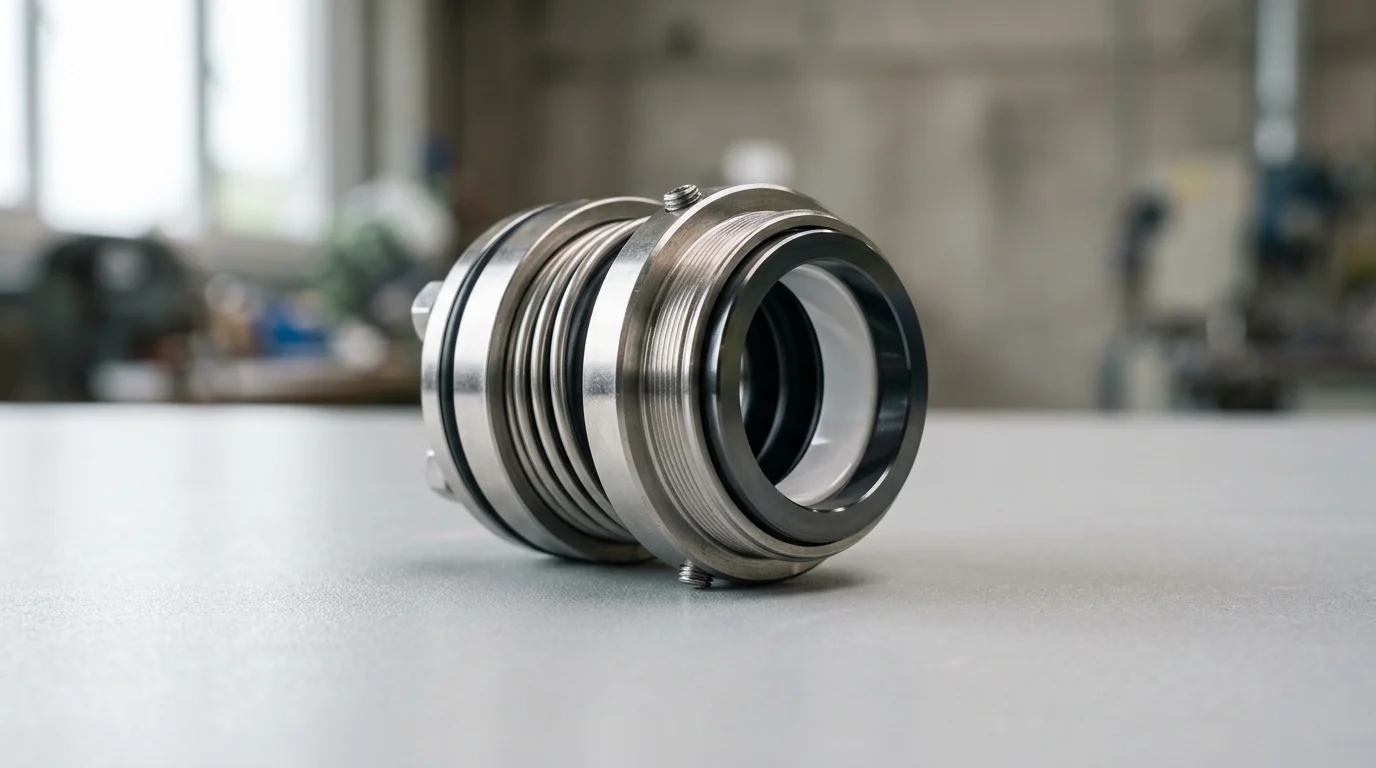
Why Mechanical Seals Fail Early
Mechanical seals are critical components in industrial rotating equipment, responsible for containing hazardous, pressurized, and expensive process fluids. Despite advancements in seal design and materials, mechanical seal failure remains the leading cause of pump downtime, accounting for approximately 69% of all centrifugal pump failures in process industries.
While a properly specified and installed mechanical seal should achieve a Mean Time Between Failures (MTBF) of 36 to 60 months, early failures—often occurring within the first 100 to 200 hours of operation—disrupt production and pose severe safety and environmental risks. Understanding the root causes of these premature failures requires distinguishing between inherent design flaws, operational shifts, and procedural errors during installation.
Common early failure symptoms
Early failure manifests through several distinct operational symptoms. The most obvious indicator is excessive leakage immediately upon startup or shortly after. While all mechanical seals weep microscopically to lubricate the faces, a visible drip rate exceeding 60 drops per minute on a standard liquid seal is a critical red flag indicating compromised face flatness or secondary seal damage.
Other symptoms include abnormal acoustic signatures, such as high-pitched squealing or popping noises, which point to fluid vaporization (flashing) between the seal faces. Thermal anomalies also serve as early warning signs; if the seal gland temperature exceeds the process fluid boiling point by 20°C or more, the seal is likely experiencing boundary lubrication failure. Technicians may also observe abnormal power consumption from the pump motor, driven by the increased friction of dry-running faces or severe shaft binding caused by improper gland torque.
Installation vs operating causes
Differentiating between installation errors and operational failures is the first step in root-cause analysis. Installation failures typically reveal themselves immediately during static pressure testing or within the first few hours of dynamic operation. These failures are characterized by instantaneous thermal shock, fractured carbon faces, or pinched O-rings resulting from improper handling.
Conversely, operational failures develop over time due to process fluctuations, such as cavitation, dry running caused by loss of suction, or chemical degradation from unapproved fluid changes.
| Failure Category | Typical Onset Time | Primary Indicators | Common Root Cause |
|---|---|---|---|
| Installation | 0 to 48 hours | Static leakage, instant face fracture, pinched elastomers | Poor alignment, incorrect torque, inadequate lubrication |
| Operational | 3 to 12 months | Gradual leakage increase, grooved faces, chemical swelling | Process fluid vaporization, cavitation, dry running |
| Systemic Design | 1 to 3 months | Repeated failures of the same mode, thermal degradation | Incorrect material selection, inadequate environmental controls |
Installation Mistakes That Cause Immediate Failure
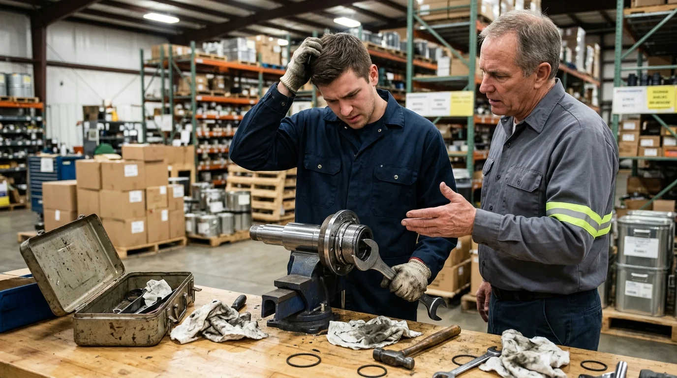
The installation of a mechanical seal requires precision engineering standards applied in a field environment. The tolerances for successful seal operation are exceptionally tight; fluid films between seal faces are often less than 1 micron thick. Consequently, seemingly minor deviations during the assembly and installation process can instantly compromise the seal’s integrity, leading to catastrophic failure upon startup.
Incorrect seal selection or material compatibility
One of the most immediate causes of failure originates before the seal even touches the shaft: incorrect material specification. Placing the wrong elastomer in a specific chemical environment leads to rapid degradation. For example, installing an EPDM O-ring in a hydrocarbon service will cause the elastomer to swell by up to 300% of its original volume within hours, extruding the rubber from its groove and locking the seal faces open.
Similarly, selecting inappropriate face materials for the application can cause immediate thermal or mechanical failure. Utilizing hard-on-hard face combinations, such as Silicon Carbide against Silicon Carbide (SiC/SiC), provides excellent abrasion resistance but possesses poor self-lubricating properties. If installed in a marginal lubrication environment without a proper barrier fluid, these faces can gall and shatter within minutes of operation.
Poor shaft alignment, runout, or torque control
Mechanical seals cannot compensate for severe mechanical deficiencies in the rotating equipment. Maximum allowable shaft runout at the seal chamber must not exceed 0.001 to 0.002 inches (0.025 to 0.050 mm) Total Indicator Reading (TIR). If a technician installs a seal on a bent shaft or over worn bearings, the resulting radial movement will force the seal faces to open and close with every revolution, destroying the microscopic fluid film and causing immediate leakage.
Furthermore, improper torque control during gland installation frequently distorts the stationary seal face. Tightening gland bolts unevenly or exceeding the manufacturer’s specified torque rating (often as low as 15 to 25 Nm depending on stud size) warps the gland plate. A distortion of just 0.0002 inches (5 microns) on the stationary face is enough to cause severe leakage, as the rotating face can no longer maintain a uniform sealing gap.
Damaged O-rings, contaminated faces, or dry starts
Secondary seals, including O-rings, wedges, and bellows, are highly susceptible to mechanical damage during installation. Pushing an O-ring over sharp shaft shoulders, threads, or keyways without a proper mounting sleeve will slice or nick the elastomer, creating an immediate leak path. Applying the wrong lubricant to aid installation—such as using petroleum jelly on EPDM—initiates chemical breakdown before the pump is even commissioned.
Contamination of the seal faces during handling is another critical error. A single fingerprint leaves behind oils and microscopic debris that can disrupt the 1-micron fluid film. Finally, failing to vent the seal chamber before startup leads to a dry start. Running a mechanical seal dry for even 30 seconds can cause face temperatures to spike above 250°C. When the process fluid finally reaches the superheated faces, the sudden cooling causes thermal shock, instantly shattering ceramic or silicon carbide components into fragments.
Process and Equipment Conditions That Damage Seals
A flawlessly installed mechanical seal will still suffer premature failure if the surrounding process conditions and equipment mechanics are not maintained within strict operational envelopes. The seal chamber acts as a micro-environment that must be carefully managed through auxiliary piping plans and rigorous equipment maintenance. When process conditions deviate, the seal inevitably becomes the weakest link in the system.
Inadequate flush, cooling, or lubrication
Mechanical seals generate significant frictional heat that must be continuously removed to prevent fluid vaporization and face distortion. API piping plans, such as Plan 11 (bypass flush) or Plan 53A (pressurized barrier fluid), are designed to manage this micro-environment. A common installation oversight is failing to commission these auxiliary systems correctly, such as leaving a flush line valved off or setting the barrier fluid pressure too low.
To maintain stable face temperatures, flush flow rates must typically achieve a minimum of 1 to 2 GPM (3.8 to 7.5 L/min) per inch of shaft diameter. If the flush is inadequate, the localized temperature rise causes the fluid film between the seal faces to flash into vapor. This loss of liquid lubrication forces the faces into dry friction, leading to rapid carbon wear, heat checking (microscopic thermal cracks) on hard faces, and eventual catastrophic destruction of the primary sealing ring.
Pipe strain, soft foot, vibration, and bearing issues
The structural integrity of the pump and its attached piping directly impacts seal longevity. Pipe strain occurs when misaligned heavy process piping is forced into connection with the pump flanges, pulling the pump casing out of its natural alignment. This casing distortion transfers directly to the seal chamber. Similarly, a soft foot condition—where the pump feet do not sit flat on the baseplate—exceeding 0.002 inches (0.05 mm) will twist the equipment casing when the mounting bolts are tightened.
These structural distortions manifest as excessive vibration and bearing wear. Mechanical seals are highly intolerant of axial and radial vibration. Equipment vibration exceeding 0.15 in/sec RMS (Root Mean Square) will accelerate the wear of the dynamic O-ring and fret the pump sleeve. Furthermore, bearing end play (axial movement) must be strictly limited to 0.001 to 0.002 inches; excessive axial movement will either over-compress the seal springs, causing coil binding and face crushing, or under-compress them, allowing the faces to blow open under pressure.
Installation mistakes vs process-related failures
Distinguishing between installation errors and process-induced damage requires a meticulous teardown and inspection of the failed seal. The wear track on the seal faces tells the story of the failure. Symmetrical, uniform wear tracks that are excessively wide or grooved generally point to process-related issues, such as poor lubrication, abrasive fluids, or continuous operation away from the pump’s Best Efficiency Point (BEP).
In contrast, asymmetrical or uneven wear tracks indicate a mechanical misalignment, often stemming from pipe strain, soft foot, or uneven gland torqueing. If the carbon face exhibits a chipped outer diameter or the drive pins are sheared, the failure was likely caused by sudden mechanical binding or a severe dry-running event at startup—classic hallmarks of commissioning and installation oversights.
How to Prevent Mechanical Seal Installation Errors
Mitigating early mechanical seal failure requires shifting from reactive maintenance to proactive, standardized installation procedures. By implementing rigorous procedural controls, precision measurement techniques, and clean-handling protocols, industrial facilities can drastically reduce the human-error variables that lead to premature equipment breakdown.
Step-by-step installation checklist
Standardizing the installation process through a documented checklist ensures consistency across all maintenance personnel. The protocol must begin with comprehensive lockout/tagout (LOTO) procedures and fluid drainage. Before the new seal is unpackaged, the technician must inspect the pump hardware. Using a dial indicator, the shaft must be checked to ensure radial runout does not exceed 0.002 inches (0.05 mm) TIR, and axial end play remains below 0.002 inches.
For component seals, accurate scribing of the shaft to determine the correct installation length is critical to ensure proper spring compression. The use of a specialized installation sleeve is mandatory to guide O-rings safely over shaft threads and keyways. Finally, gland nuts must be tightened using a calibrated torque wrench in an alternating, crisscross pattern to the manufacturer’s exact specifications, preventing the microscopic face distortion that causes immediate static leakage.
Clean handling and seal face protection
Mechanical seals must be handled with the same care as precision optical instruments. The assembly area should be isolated from grinding, welding, or dusty environments. Technicians must wear clean, lint-free nitrile gloves when handling the seal faces; bare hands transfer natural oils and moisture that attract abrasive atmospheric dust.
Seal faces should never be placed face-down on a workbench. If cleaning is necessary, technicians should use only approved, fast-evaporating solvents (such as isopropyl alcohol) and lint-free wipes. Applying a light film of approved system-compatible lubricant to the faces is permissible only if explicitly required by the manufacturer; otherwise, faces should remain perfectly clean and dry to ensure the designed fluid film can establish itself upon startup.
Commissioning checks for flush flow and leakage
The installation process is not complete until the pump is safely commissioned. Before the motor is energized, the seal chamber must be thoroughly vented to expel all trapped air, ensuring the seal faces are fully submerged in liquid. A static pressure test should be conducted by opening the suction and discharge valves and holding the pump at static system pressure for a minimum of 10 minutes. Zero visible leakage should be observed during this holding period.
During the static test, the technician should rotate the pump shaft by hand to verify there is no mechanical binding or internal rubbing. Once the pump is energized, auxiliary flush systems must be immediately verified. Technicians should use flow meters and infrared thermometers to confirm that the API piping plan is delivering the specified 1 to 2 GPM flush rate and that the gland temperature stabilizes within acceptable limits, confirming the seal is operating in a healthy, lubricated environment.
When to Reinstall, Upgrade, or Redesign
Even with perfect installation practices, certain pumping applications present environments too hostile for standard mechanical seal configurations. When early failures persist despite rigorous adherence to installation protocols, maintenance and reliability engineering teams must evaluate whether to continue replacing seals in-kind or to invest in systemic upgrades and redesigns.
Signs of recurring root-cause problems
Reliability engineers must meticulously track MTBF data to identify chronic bad actors. If a specific pump’s mechanical seal exhibits an MTBF of less than 12 months, or if the exact same failure mode—such as FKM elastomer degradation or continuous dry-running heat checks—occurs three consecutive times, the root cause is systemic rather than procedural.
Other indicators of a required redesign include frequent changes in the process fluid composition, temperature spikes that exceed the original equipment specifications, or the introduction of abrasive slurries that the current seal was not engineered to handle. Continuing to install the same seal in a fundamentally altered process environment guarantees ongoing early failures and escalating maintenance costs.
Cost, downtime, and reliability trade-offs
Upgrading a seal involves analyzing the total cost of ownership (TCO) versus the upfront capital expenditure. Transitioning from a basic component seal to a pre-assembled cartridge seal typically incurs a 20% to 40% higher initial purchasing cost. However, cartridge seals eliminate the need to manually set spring compression and handle fragile faces, reducing installation-related errors by up to 70%.
When evaluating this trade-off, facilities must factor in the cost of downtime. In petrochemical and refining operations, lost production due to pump failure can range from $10,000 to $50,000 per hour. Compared to these staggering downtime penalties, the $1,500 to $3,000 premium for a highly engineered, dual-cartridge seal system with a dedicated barrier fluid plan is rapidly justified by the prevention of a single premature failure.
Decision framework to reduce repeat failures
To transition from reactive replacements to strategic upgrades, facilities should employ a structured decision framework based on the specific failure diagnostics. This framework guides engineers in selecting the appropriate technological intervention based on the operational symptoms observed during teardown.
| Observed Condition | Current Configuration | Recommended Upgrade | Expected Reliability Impact |
|---|---|---|---|
| Frequent installation errors, incorrect spring tension | Component Seal | Single Cartridge Seal | Eliminates setting errors; increases MTBF by 12-24 months |
| Fluid flashing, dry running, atmospheric hazards | Single Seal (Plan 11) | Dual Seal with Barrier Fluid (Plan 53A) | Provides independent face lubrication; zero process emissions |
| Abrasive wear, grooved faces from suspended solids | Carbon vs. Ceramic Faces | SiC vs. SiC with Cyclone Separator (Plan 31) | Highly resistant to abrasion; extends face life by 300% |
| Elastomer swelling, chemical attack | FKM or EPDM O-rings | FFKM (Perfluoroelastomer) O-rings | Universal chemical resistance; prevents secondary seal failure |
By systematically applying this framework, industrial facilities can break the cycle of early mechanical seal failures, ensuring that maintenance budgets are spent on long-term reliability rather than perpetual, reactive repairs.
Key Takeaways
- Treat leakage above about 60 drops per minute as a critical warning sign and stop the pump for inspection before face or elastomer damage worsens.
- Investigate failures that occur within the first 0 to 48 hours as likely installation errors involving alignment, torque, lubrication, handling, or O-ring placement.
- Monitor seal gland temperature because operation 20°C or more above the process fluid boiling point can indicate lubrication failure or flashing at the faces.
- Use startup symptoms such as squealing, popping, power draw increases, and instant leakage to separate installation defects from longer-term operating problems.
- Apply precise installation procedures because the lubricating film between mechanical seal faces is often less than 1 micron thick and easily disrupted.
- Aim for a properly specified and installed seal life of 36 to 60 months, and treat failures within 100 to 200 hours as premature events requiring root-cause analysis.
Frequently Asked Questions
How soon can installation-related mechanical seal failure appear?
Installation-related failures often appear during static pressure testing or within the first 0 to 48 hours of operation. Immediate leakage, cracked carbon faces, pinched O-rings, or abnormal heat at startup usually point to assembly, alignment, lubrication, or torque errors.
What leakage rate suggests a mechanical seal problem?
A small amount of microscopic weeping is normal because the seal faces need lubrication. However, visible leakage above about 60 drops per minute on a standard liquid seal is a serious warning sign that face flatness, elastomers, or installation accuracy may be compromised.
Why does a mechanical seal squeal or pop after startup?
Squealing or popping often indicates flashing or vaporization between the seal faces. This can happen when the faces run too hot, the flush plan is inadequate, suction conditions are poor, or the seal has been installed in a way that prevents proper lubrication.
What is the expected service life of a properly installed mechanical seal?
When correctly selected, installed, and operated, a mechanical seal can often achieve a Mean Time Between Failures of about 36 to 60 months. Failures within the first 100 to 200 operating hours usually indicate installation, operating, or specification problems.
How can technicians tell installation failure from operating failure?
Installation failures usually show up immediately or within hours as static leakage, face fracture, overheating, or damaged O-rings. Operating failures typically develop over months and are linked to cavitation, dry running, process changes, chemical attack, or unstable pump conditions.

Post time: Jul-24-2026