


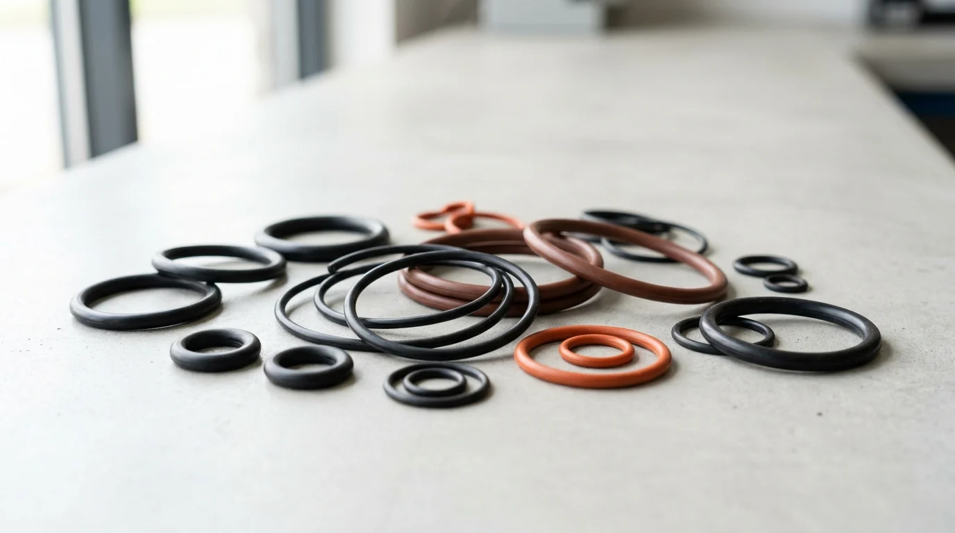
Why O-Ring Seals Fail During Pump Start and Stop
Pump systems subjected to frequent start-and-stop cycles place extraordinary demands on sealing components. While continuous operation allows systems to achieve thermal and hydraulic equilibrium, cyclic duty introduces severe transient forces. The severity of these transients depends heavily on the equipment; for instance, direct-on-line centrifugal pumps experience much harsher start-stop shocks than soft-started or positive displacement systems. During pump startup, fluid inertia and sudden valve actuations can generate severe pressure surges that significantly exceed nominal operating pressures. O-ring seals must absorb these rapid mechanical and hydraulic shocks without losing contact stress against the mating hardware.
How Start-Stop Transients Affect Seal Performance
In a standard centrifugal pump, the shaft can reach full rotational velocity in a fraction of a second, creating localized high-pressure zones at the discharge and sudden vacuum conditions near the suction eye. This rapid acceleration forces elastomeric O-rings to deform instantaneously to seal dynamic clearances. However, polymers possess inherent viscoelastic hysteresis, meaning their physical response lags behind the applied force. If the transient pressure spike outpaces the elastomer’s reaction time, momentary fluid bypass occurs, allowing fluid to escape before the seal fully energizes.
Key Failure Modes: Leakage, Compression Set, and Extrusion
When seals fail to accommodate these rapid transients, they typically succumb to leakage, compression set, or extrusion. Leakage during startup often results from a loss of initial interference squeeze, exacerbated by fluid chilling during the offline period.
Over time, the elastomer may suffer compression set, permanently losing its ability to return to its original cross-section after being repeatedly compressed. While general guidelines suggest a compression set exceeding 20% to 25% of the original cross-sectional diameter compromises seal integrity, this threshold varies based on application criticality and specific testing standards (such as ASTM D395 Method B for constant deflection versus Method A for constant load).
Extrusion, conversely, is driven by dynamic pressure spikes that force the O-ring material into the microscopic clearance gap between the mating metal components. Repeated extrusion cycles during start and stop phases eventually shear the polymer, leading to catastrophic seal rupture.
Mechanical and Hydraulic Causes of O-Ring Seal Failure
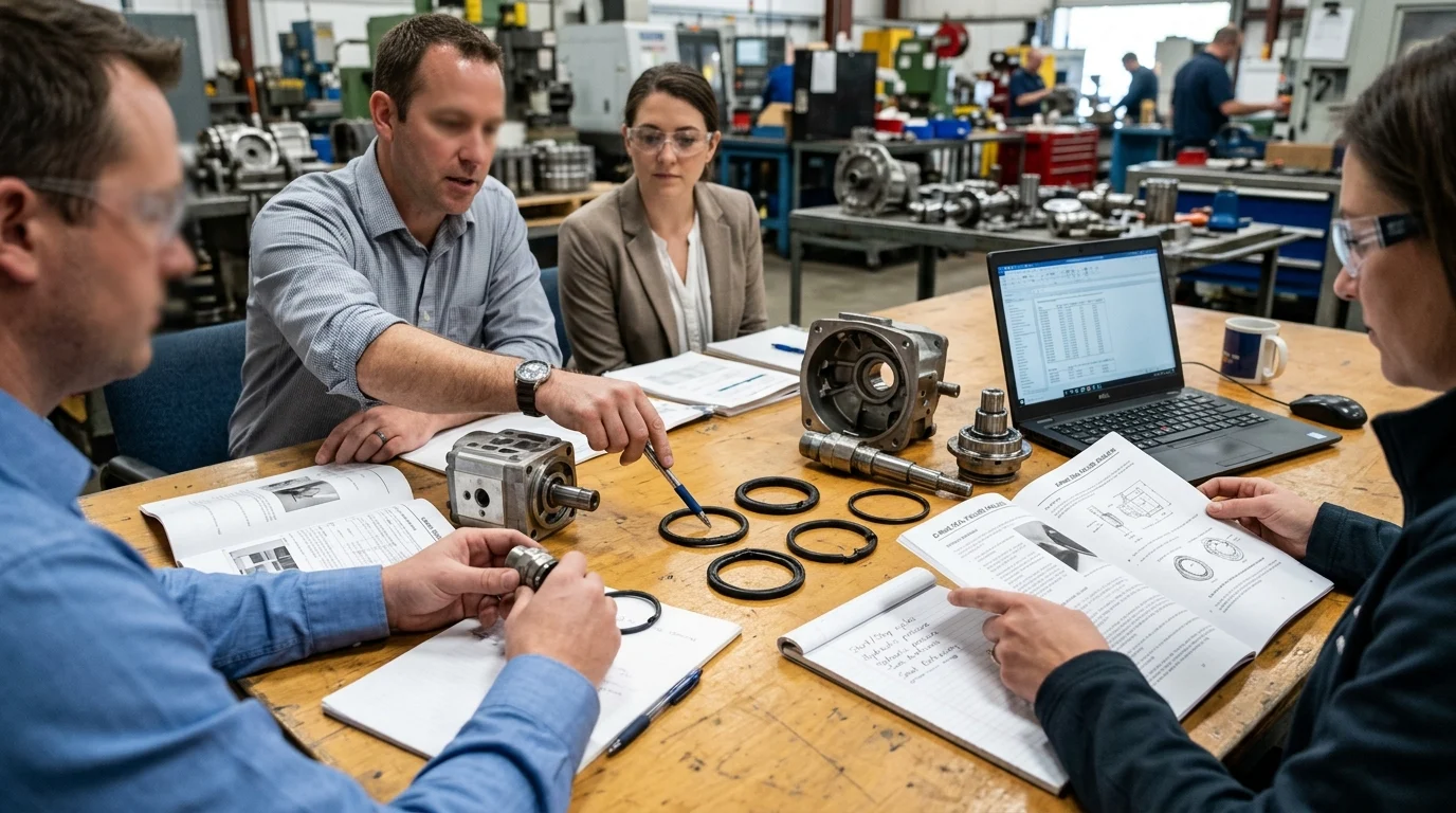
A single catastrophic event rarely destroys an O-ring in a cyclic pump system. Instead, cumulative mechanical and hydraulic stressors exploit the limitations of the elastomer and the gland geometry. Understanding these root causes requires examining the micro-environment of the seal, where clearances as small as 0.002 inches (0.05 mm) can become fatal extrusion paths when subjected to extreme transient pressure spikes.
Pressure Spikes, Vacuum Conditions, and Cavitation
Hydraulic transients, specifically water hammer and cavitation, aggressively destroy elastomeric seals. Sudden pump trips or rapid valve closures send shockwaves through the fluid column, generating localized pressure spikes that physically ram the O-ring against the downstream side of the gland. Conversely, vacuum conditions during pump coast-down can pull the O-ring away from its seating surface.
Cavitation introduces an even more aggressive threat: as vapor bubbles collapse near the seal interface, they generate microscopic fluid jets with localized impact pressures high enough to severely erode the polymer surface. These micro-jets leave a pitted, sponge-like appearance that eventually leads to structural failure.
Shaft Movement, Vibration, and Misalignment
Mechanical dynamics during start and stop sequences introduce severe radial and axial deflection. As a pump impeller accelerates, it frequently passes through critical speeds that induce transient shaft vibration. If the shaft runout is excessive—for example, exceeding 0.005 inches (0.13 mm) Total Indicator Reading (TIR) during startup—the O-ring is subjected to rapid compression and relaxation cycles.
Because elastomer recovery times vary significantly by compound formulation and operating temperature, high-frequency vibration can outpace the material’s ability to rebound. For example, a standard nitrile compound might require milliseconds to recover its shape, whereas a transient vibration gap opens in microseconds, momentarily creating a leak path. Furthermore, repeated axial movement of the shaft can cause the O-ring to roll within its groove, leading to spiral failure—a condition where the seal twists and eventually tears along its circumference.
Temperature Swings, Dry Running, and Fluid Changes
Temperature fluctuations during cyclic operation severely degrade elastomer integrity. Pumps starting dry or operating with low flow experience rapid frictional heating at the seal interface. Because the coefficient of thermal expansion for typical elastomers is approximately ten times greater than that of carbon steel, the O-ring expands significantly, overfilling the gland and increasing friction (a thermal dynamic further detailed in the Gland Fill section below).
When the pump stops and cools, the elastomer contracts. Repeated thermal cycling accelerates polymer cross-linking, transforming a pliable 70-durometer (Shore A) O-ring into a brittle, glass-like component incapable of maintaining a dynamic seal during the next startup sequence. Mitigating this dry-running damage requires proper startup procedures, such as implementing flush plans, utilizing barrier fluids, or establishing pre-lubrication protocols to ensure the seal interface is adequately lubricated before the shaft rotates.
How to Compare O-Ring Materials and Groove Designs
Defending against mechanical and hydraulic failure mechanisms requires precise alignment between the elastomer’s properties and the gland’s mechanical design. Selecting the correct O-ring involves evaluating durometer hardness, tensile strength, and extrusion resistance, while simultaneously optimizing gland fill and squeeze parameters to accommodate thermal and pressure variations.
Elastomer Properties That Matter in Pump Service
The physical characteristics of the elastomer dictate its survivability in pump service. Durometer hardness, measured on the Shore A scale, is a primary indicator of extrusion resistance. While a standard 70 Shore A compound offers excellent flexibility and low-pressure sealing, it is highly susceptible to extrusion under cyclic high-pressure transients.
Upgrading to a 90 Shore A compound increases the material’s modulus and extrusion resistance, though it requires greater compressive force to achieve initial sealing. Tensile strength and elongation at break are equally critical; materials with high tear resistance are better equipped to withstand the shear forces generated during rapid pump startup.
Gland Fill, Squeeze, Stretch, and Extrusion Gap
Gland geometry must accommodate the physical realities of the elastomer under operational stress. The ideal volumetric gland fill should not exceed 85% to 90%, ensuring adequate void space for the elastomer’s thermal expansion discussed earlier. If the gland reaches 100% fill, the expanding O-ring will exert massive outward pressure, potentially distorting the metal hardware or fracturing the seal.
Squeeze—the percentage of cross-sectional compression—must be tightly controlled. Static seals typically require 15% to 30% squeeze, whereas dynamic applications are limited to 8% to 16% to minimize frictional heat. Additionally, installing an O-ring with excessive stretch on its inside diameter reduces its cross-section and increases internal material stress, which rapidly accelerates degradation and failure in hot pump applications.
Comparison Criteria for Selecting O-Rings
Material selection requires weighing chemical compatibility against mechanical durability. Note that the temperature ranges and performance characteristics in the following table are illustrative; actual limits vary significantly based on the specific compound grade, formulation, and test conditions. The table compares common elastomers used in cyclic pump applications based on their general operational thresholds:
| Elastomer Material | Typical Temp Range | Extrusion Resistance | Relative Cost | Common Pump Application |
|---|---|---|---|---|
| Nitrile (NBR) | -40 to +108 °C (-40 to +226 °F) | Moderate | Low | General water, light oils |
| Fluorocarbon (FKM) | -26 to +205 °C (-15 to +401 °F) | High | Medium | Hydrocarbons, high-temp fluids |
| Ethylene Propylene (EPDM) | -55 to +150 °C (-67 to +302 °F) | Moderate | Low | Hot water, steam, alkalis |
| Perfluoroelastomer (FFKM) | -15 to +320 °C (+5 to +608 °F) | Very High | Very High | Aggressive chemicals, extreme heat |
Root-Cause Analysis for Failed O-Ring Seals
When an O-ring fails during cyclic pump operation, replacing the seal without identifying the underlying cause guarantees a repeat failure. Root-cause analysis (RCA) transforms an unexpected downtime event into actionable engineering data. Industry experience indicates that a vast majority of failed elastomeric seals retain physical evidence of the failure mechanism on their surface, provided they are extracted and examined correctly.
Failure Evidence to Document Before Removal
The diagnostic process must begin before the failed seal is removed from its gland. Maintenance personnel should document the exact orientation of the O-ring, noting whether it has been extruded to the low-pressure side or twisted within the groove. Photographs of the seal in situ provide critical context.
Micrometer measurements of the extrusion gap and gland depth should be taken to verify that the hardware has not yielded or worn out of tolerance. Extracting the seal with sharp metal picks can introduce artificial cuts and scratches, masking the true failure mode; brass or plastic extraction tools are mandatory for preserving forensic evidence.
Linking Damage Patterns to Operating Conditions
The physical condition of the extracted O-ring serves as a direct map to the system’s operating conditions. To accurately diagnose the failure, engineers must match visual damage patterns to hydraulic and mechanical phenomena.
| Visual Damage Pattern | Primary Failure Mode | Typical Root Cause in Cyclic Pumps |
|---|---|---|
| Flattened cross-section | Compression Set | Excessive thermal cycling; incompatible material |
| “Nibbled” or flaking edges | Extrusion / Clearance | High-pressure spikes exceeding material modulus |
| Deep spiral cuts | Spiral Failure | Excessive shaft runout; low speed dry running |
| Surface cracking with moderate hardening | Thermal Fatigue | Repeated heating and cooling cycles from intermittent operation |
| Hard, brittle, with deep radial cracks | Thermal Degradation | Continuous exposure to temperatures exceeding the elastomer’s limit (e.g., prolonged dry running) |
Using Inspection Data and Seal History
Physical evidence must be correlated with operational data to establish a definitive root cause. Reviewing SCADA systems or programmable logic controller (PLC) logs can reveal transient pressure spikes, temperature excursions, or vibration anomalies that align with the physical damage.
For instance, in one cooling water pump application, O-rings exhibited severe extrusion despite nominal operating pressures remaining well within the material’s limits. By correlating the exact timestamps of seal failures with PLC logs, engineers discovered that an automated downstream valve was closing 0.5 seconds before the pump motor de-energized. This sequencing error generated an undocumented 400-psi (27.6 bar) water hammer spike during every shutdown. Adjusting the PLC timing to delay the valve closure eliminated the pressure spike and resolved the recurring extrusion failures.
Combining forensic inspection with the pump’s maintenance and operational history ensures that corrective actions address the systemic issue rather than just the symptom. When historical data and physical evidence point to systemic operational stressors rather than isolated incidents, maintenance teams must pivot from simply replacing seals to redesigning the sealing environment.
When to Redesign, Respecify, or Change Maintenance Practices
Upgrading a sealing system requires a strategic shift from reactive maintenance to proactive engineering. When failure analysis dictates that the operational environment exceeds the capabilities of the current design, engineers must evaluate alternative geometries, tighter material specifications, and revised maintenance intervals. Implementing these changes can dramatically alter the lifecycle of the equipment, often extending the Mean Time Between Failures (MTBF) from a problematic few months to years of reliable service.
When Standard O-Rings Are No Longer Suitable
Standard O-rings, while versatile, possess inherent limitations in highly dynamic, cyclic environments. When standard toroidal profiles fail repeatedly due to spiral twisting or severe extrusion, engineers must transition to alternative geometries.
Incorporating polytetrafluoroethylene (PTFE) backup rings on the low-pressure side of the gland effectively reduces the extrusion gap to zero, allowing standard elastomers to survive significant pressure transients. Alternatively, replacing standard O-rings with D-rings, X-rings (quad rings), or T-seals provides a wider, more stable footprint within the gland, virtually eliminating the risk of spiral failure during frequent pump startups.
Sourcing Quality and Material Certification Checks
Upgrading the seal design is futile if the component quality is inconsistent. Rigorous sourcing and material certification checks are critical for high-reliability pump systems. Procurement specifications must mandate batch traceability and specific curing processes; for example, specifying a peroxide-cured EPDM over a sulfur-cured variant yields superior thermal stability and lower compression set.
Furthermore, dimensional quality control is paramount. Engineers should reject O-rings with a parting line flash exceeding 0.003 inches (0.076 mm), as excessive flash disrupts the dynamic sealing line and provides an initiation point for shear failure during shaft rotation.
Balancing Lifecycle Cost, Downtime Risk, and Reliability
The decision to respecify a sealing system ultimately hinges on evaluating the Total Cost of Ownership (TCO). While a standard NBR O-ring may cost a few dollars, an engineered Perfluoroelastomer (FFKM) seal or a custom-machined T-seal represents a higher initial investment. However, this upfront material premium is negligible compared to the costs of unplanned pump outages, lost production, and environmental remediation from a hazardous fluid leak. By aligning seal material science, gland engineering, and rigorous failure analysis, industrial facilities can significantly mitigate risk and improve the reliability of their pump networks, ensuring that sealing components predictably withstand the mechanical and hydraulic demands of start-stop cyclic operation.
Key Takeaways
- Evaluate pump start-stop severity because direct-on-line centrifugal pumps typically impose harsher transient shock than soft-started or positive displacement systems.
- Check O-ring compression set during maintenance, since values above roughly 20% to 25% of the original cross-section can compromise sealing reliability.
- Control hydraulic transients with proper valve timing, soft starts, and system design to reduce water hammer, cavitation, and vacuum-related seal lift-off.
- Minimize extrusion risk by maintaining tight gland clearances and adding backup rings when pressure spikes can force elastomer into clearance gaps.
- Select O-ring materials and mechanical seal designs based on cyclic pressure, temperature, chemical exposure, and downtime cooling rather than nominal operating pressure alone.
Frequently Asked Questions
Why do O-rings leak when a pump starts?
Startup can create pressure spikes, suction-side vacuum, and rapid shaft acceleration before the elastomer fully responds. If the O-ring cannot energize fast enough or has lost squeeze during downtime, brief fluid bypass and visible leakage can occur.
What is compression set in an O-ring seal?
Compression set is the permanent flattening of an O-ring after repeated compression. When it exceeds roughly 20% to 25% of the original cross-section, depending on standards and application criticality, the seal may no longer maintain reliable contact stress.
How do pressure spikes cause O-ring extrusion?
Dynamic pressure spikes can force elastomer material into small clearance gaps between metal components. Repeated start-stop cycles shear the extruded material, eventually causing cracking, nibbling, leakage, or catastrophic rupture.
Can pump shutdown damage O-ring seals?
Yes. Shutdown can create reverse pressure, vacuum conditions, water hammer, and thermal contraction. These conditions may pull the O-ring away from its sealing surface or accelerate wear if the gland design and material are not suited to cyclic duty.
How can frequent start-stop seal failures be reduced?
Use proper gland clearances, compatible elastomers, anti-extrusion backup rings where needed, controlled valve timing, soft-start drives, and seal designs rated for cyclic pressure and temperature changes.

Post time: Oct-16-2026