


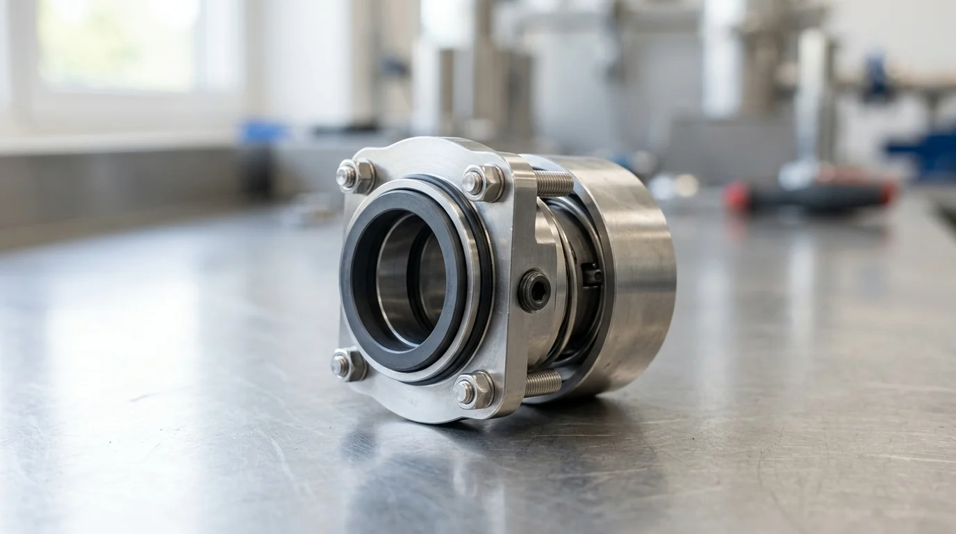
Why Mechanical Seals Fail in Chemical Plants
In chemical processing facilities, rotating equipment reliability is inextricably linked to fluid containment. Centrifugal pumps account for the vast majority of fluid transfer operations, and within these pumps, mechanical seals are a primary point of vulnerability. Seal failures often drive a significant portion of centrifugal pump maintenance. While benign applications might run for years without issue, mechanical seals in harsh chemical environments can fail in a fraction of that time if not meticulously specified and operated. Failure rates vary enormously depending on plant maturity, maintenance culture, and the specific chemical processes involved.
The fundamental challenge lies in the operating principle of mechanical seals: they rely on a microscopic fluid film—typically 0.5 to 2.0 microns thick—to lubricate and cool the rotating and stationary faces. In chemical plants, this lubricating fluid is often highly corrosive, volatile, abrasive, or prone to phase changes. When process conditions disrupt this delicate fluid film, face friction escalates, leading to rapid thermal degradation and containment loss.
How to Define Mechanical Seal Failure
Defining a mechanical seal failure in a chemical plant extends far beyond observing a visible puddle of product on the baseplate. Instead, failure occurs when a seal breaches specific environmental, operational, or safety thresholds. For instance, volatile organic compounds (VOCs) are heavily regulated under directives such as the EPA’s Method 21. A seal may appear dry to the naked eye but is classified as a failure if it registers fugitive emissions exceeding 500 parts per million (ppm) on a photoionization detector.
Furthermore, auxiliary system metrics provide concrete failure indicators. In dual seal arrangements utilizing an API Plan 53A pressurized barrier fluid system, an unacceptable rate of barrier fluid consumption—such as exceeding 20 to 50 milliliters per day—indicates internal face degradation even if no process fluid escapes to the atmosphere. Recognizing these measurable thresholds allows plants to identify incipient failures before they escalate into severe containment breaches or regulatory violations.
Why Seal Reliability Affects Production Uptime
The reliability of mechanical seals is a direct driver of overall production uptime and facility profitability. Pumping systems are the circulatory system of a chemical plant; when a critical transfer pump goes offline due to a seal leak, downstream reactors and distillation columns are starved of feed, forcing rate reductions or complete unit shutdowns. The financial impact of these disruptions is severe, with unplanned downtime in continuous chemical processing frequently resulting in substantial lost yield.
Beyond the immediate loss of production, reactive seal replacements carry heavy secondary costs. A single pump overhaul, factoring in labor, decontamination protocols, replacement parts, and crane rigging, represents a significant maintenance expense. Additionally, when a seal fails unexpectedly, the escaping chemical inventory poses safety risks to personnel and can trigger mandatory reporting to environmental agencies, potentially resulting in fines. Consequently, improving seal reliability directly stabilizes production schedules and protects profit margins.
Process Conditions That Drive Seal Failure

The longevity of a mechanical seal is dictated primarily by the physical and chemical properties of the process fluid it is tasked with containing. Unlike utility water applications, chemical streams introduce complex variables including extreme pH levels, high specific gravity, suspended solids, and volatile vapor pressures. Understanding how these fluid characteristics interact with seal faces and elastomers is critical for diagnosing premature failures.
Corrosion, Crystallization, and Polymerization Risks
Corrosive fluids, such as sulfuric acid, hydrochloric acid, and concentrated sodium hydroxide, aggressively attack standard metallurgies. If a seal’s metal components—such as the drive collar, springs, or bellows—are not properly specified (e.g., using Alloy 20 or Hastelloy C-276 instead of 316 stainless steel), the structural integrity of the seal will degrade rapidly, leading to loss of face compression.
Crystallization and polymerization present equally destructive mechanical risks. Fluids like caustic soda or urea will crystallize upon exposure to ambient air or slight temperature drops. These hard crystals form on the atmospheric side of the seal faces, acting as a grinding paste that rapidly wears away carbon or silicon carbide surfaces. Similarly, monomers such as styrene and butadiene are prone to polymerization. Under the localized heat and shear stress of the seal faces, these fluids cross-link into sticky, solid polymers that bind the seal faces together, causing severe mechanical damage upon the next pump start-up.
Temperature Swings, Dry Running, and Cavitation
Thermal instability is a leading cause of fluid film breakdown. When a pump operates near the vapor pressure of the process fluid, even minor temperature swings can cause the fluid to flash into a gas directly between the seal faces. Because gases provide virtually no lubrication, the faces experience dry running. Dry running for as little as 30 to 60 seconds can cause localized temperatures to spike by over 150°C, leading to thermal distortion or ‘heat checking’—a network of microscopic radial cracks on hard face materials.
Cavitation, caused by insufficient Net Positive Suction Head Available (NPSHa), exacerbates seal failure by introducing severe mechanical shock. When vapor bubbles collapse within the pump casing, they generate high-frequency vibrations that easily exceed the standard operational threshold of 0.15 in/sec RMS. This intense vibration is transmitted directly through the pump shaft to the mechanical seal, fracturing brittle face materials like silicon carbide and accelerating the fatigue failure of welded metal bellows.
How to Compare Process Fluid Risks
To systematically mitigate process-driven failures, maintenance programs must categorize process streams by their inherent risks and align them with specific seal architectures. The table below outlines common chemical fluid profiles, their associated risks, and the typical failure mechanisms they induce.
| Process Fluid Category | Primary Seal Risk Factor | Typical Failure Mechanism | Required Mitigation Strategy |
|---|---|---|---|
| Light Hydrocarbons / VOCs | High volatility, low lubricity | Flashing, dry running, heat checking | Dual pressurized seals, API Plan 53/54 |
| Caustics & Salts | Crystallization at ambient temp | Abrasive face wear, dynamic O-ring hang-up | Quench systems (API Plan 62), hard face pairings |
| Monomers (e.g., Styrene) | Polymerization under shear/heat | Faces gluing together, elastomer degradation | Temperature control, barrier fluid systems |
| Strong Acids (pH < 2) | Aggressive chemical attack | Metal component dissolution, elastomer swelling | Exotic alloys (Hastelloy), FFKM O-rings |
By mapping these fluid risks, engineers can move away from one-size-fits-all seal specifications and implement targeted solutions that address the specific physics and chemistry of the pumped medium.
Seal Design, Materials, and Support Systems
Mitigating the harsh process conditions found in chemical plants requires a holistic approach to seal selection. This encompasses the physical architecture of the seal, the metallurgical and elastomeric composition of its components, and the external piping support systems that regulate its operating environment. A deficiency in any of these three pillars will inevitably compromise the seal’s lifespan.
When to Use Single or Dual Mechanical Seals
The decision to utilize a single or dual mechanical seal hinges on the toxicity, volatility, and lubricity of the process fluid. Single mechanical seals utilize one set of mating faces and rely entirely on the process fluid for lubrication. They are cost-effective and suitable for benign, non-hazardous fluids with good lubricating properties, provided the fluid’s vapor pressure is at least 1.5 bar (approx. 22 psi) below the stuffing box pressure to prevent flashing.
Dual mechanical seals are mandatory for hazardous chemicals, carcinogens, or fluids with poor lubricity. A dual unpressurized seal (tandem arrangement) uses a buffer fluid operating at a pressure lower than the process fluid, serving as a safety backup and emission containment measure. Conversely, a dual pressurized seal (double arrangement) utilizes a barrier fluid pressurized to 1.5 to 2.0 bar (20 to 30 psi) above the maximum stuffing box pressure. This ensures that any leakage across the inner faces consists of clean barrier fluid entering the process, completely isolating the hazardous chemical from the atmosphere and providing a pristine lubricating film for the seal faces.
Seal Face Materials, Elastomers, and Metallurgy
Material selection dictates a seal’s ability to withstand chemical attack and thermal stress. For seal faces, the most common pairing in chemical applications is premium-grade Carbon graphite running against Silicon Carbide (SiC). This pairing offers excellent natural lubricity and is forgiving under marginal lubrication. However, for highly abrasive or viscous fluids, a hard-on-hard pairing of Silicon Carbide versus Silicon Carbide is required, despite its lower tolerance for dry-running conditions.
Elastomer selection is equally critical, as O-rings represent the most chemically vulnerable components of the seal. The table below compares standard elastomeric materials used in chemical mechanical seals, detailing their thermal limits and chemical compatibility.
| Elastomer Material | Temp Limit (°C) | Chemical Compatibility Profile | Common Limitations |
|---|---|---|---|
| FKM (Viton™) | 204°C | Good for oils, lubricants, and broad chemical use. | Poor resistance to steam, hot water, and amines. |
| EPDM | 150°C | Excellent for hot water, steam, and dilute acids/alkalis. | Rapid swelling and failure in petroleum-based fluids. |
| FFKM (Kalrez™) | 327°C | Near-universal chemical resistance; used in severe acids/solvents. | Extremely high cost; susceptible to rapid gas decompression. |
| PTFE (Teflon™) | 260°C | Universal chemical inertness. | Lacks elasticity; requires specialized spring-energized designs. |
Flush Plans, Barrier Fluids, and Buffer Fluids
Mechanical seals rarely survive in chemical applications without an external support system, defined by API 682 piping plans. These plans manage the environment around the seal faces by controlling temperature, pressure, and fluid cleanliness. For single seals, an API Plan 11 (bypass flush from pump discharge) is the default, ensuring adequate flow to dissipate the heat generated by face friction.
For dual seals, managing the barrier or buffer fluid is paramount. An API Plan 52 provides an unpressurized buffer fluid for tandem seals, while an API Plan 53A utilizes a gas-charged accumulator to supply pressurized barrier fluid to double seals. The selection of the barrier fluid itself is vital; it must be chemically compatible with the process in case of inner seal leakage, and it must possess optimal viscosity—typically less than 30 cSt at operating temperature—to ensure it can penetrate the microscopic gap between the seal faces without generating excessive hydraulic shear heat.
Installation and Operating Causes of Failure
Even a perfectly specified mechanical seal constructed from premium materials will fail prematurely if it is installed incorrectly or subjected to abusive operational transients. The tolerances within a mechanical seal are microscopic, meaning that minor deviations in pump geometry or operational stability translate into significant mechanical forces at the seal faces.
Installation Errors That Distort Seal Faces
Mechanical seals require a highly precise mechanical environment to function. The most common installation error is the uneven torquing of the gland plate bolts. Because the stationary seal face is mounted within the gland, applying uneven torque—or exceeding the recommended 15 to 20 Nm—can distort the stationary face by just 1 to 2 microns. Since the fluid film is often only 0.5 microns thick, this microscopic distortion causes the rotating face to contact the stationary face unevenly, resulting in immediate leakage and rapid wear.
Furthermore, pump shaft condition is critical. Before installing a seal, technicians must verify that radial shaft runout does not exceed 0.05 mm (0.002 inches) Total Indicator Reading (TIR). Excessive runout forces the dynamic O-ring to constantly slide back and forth along the shaft to maintain face contact, a phenomenon known as ‘fretting.’ This not only wears out the elastomer but eventually grooves the metal shaft sleeve, creating a permanent leak path.
Start-Up, Cleaning, and Pump Operation Issues
The manner in which a pump is operated heavily influences seal life. Operating a centrifugal pump too far from its Best Efficiency Point (BEP) is highly destructive. When a pump operates below 60% or above 110% of its BEP, hydraulic forces become unbalanced, causing the shaft to deflect radially. This deflection alters the perpendicularity of the seal faces, forcing them to open on one side and crush together on the other.
Cleaning and start-up procedures also introduce significant risks. In chemical plants utilizing Clean-in-Place (CIP) or Steam-in-Place (SIP) protocols, injecting high-temperature steam into a cold pump can cause extreme thermal shock, cracking silicon carbide faces. Additionally, failing to properly vent the stuffing box before start-up traps a pocket of air or vapor around the seal. When the pump engages, the seal faces operate completely dry until the vapor pocket is cleared, frequently damaging the carbon face within seconds.
Practical Mechanical Seal Troubleshooting Steps
When a seal fails, performing a structured visual inspection of the removed components is essential for root cause analysis. A seal should never simply be replaced without examining the damage. For instance, if the carbon face exhibits deep, localized pitting or ‘blistering,’ it is a definitive sign that the fluid film is vaporizing and expanding violently within the pores of the carbon, indicating a need for better cooling or a higher stuffing box pressure.
Similarly, examining the elastomers provides critical clues. An O-ring that appears swollen or sticky indicates chemical incompatibility with the process fluid or the cleaning solvents. Conversely, an O-ring that has a flattened, squared-off cross-section has suffered from compression set due to excessive temperature. By methodically troubleshooting these physical symptoms, facilities can adjust the seal design or operating procedures to prevent recurring failures.
How to Reduce Mechanical Seal Failure Rates
Transforming a chemical plant’s maintenance culture from reactive replacement to proactive reliability requires a data-driven approach to mechanical seal management. By systematically tracking performance metrics, engineering upgrades based on root cause analysis, and evaluating total lifecycle costs, facilities can dramatically reduce their failure rates and associated downtime.
Failure Data Plants Should Track
Effective reliability programs are built on accurate, granular data collection. Facilities must track the Mean Time Between Failures (MTBF) for every pump, categorizing failures by specific unit, process fluid, and seal type. A low plant-wide average MTBF in chemical applications indicates systemic issues that require intervention. Modern failure reduction programs increasingly rely on seal monitoring technology. Integrating temperature, pressure, and acoustic emission sensors provides real-time visibility into the seal environment, offering early warnings of dry running, bearing wear, or cavitation before they cause irreversible damage.
For dual seal systems, logging barrier fluid consumption is one of the most effective predictive maintenance tools available. A healthy dual seal operating on an API Plan 53A system should consume minimal barrier fluid daily. If consumption rates creep upward, it is a clear quantitative indicator that the inner seal face is degrading. Scheduling a planned maintenance intervention at this stage prevents an unexpected breakdown and avoids the environmental hazards of a total containment breach.
When to Repair, Upgrade, or Redesign
Deciding whether to repair, upgrade, or completely redesign a seal installation depends on the failure analysis and historical performance. If a seal fails after years of continuous service and exhibits normal, even face wear, a standard repair (lapping the faces and replacing elastomers) is the most cost-effective path. However, if the same pump experiences repeated failures every few months, merely replacing the seal in kind will not solve the underlying problem.
Upgrades should be targeted at the specific failure mode identified during troubleshooting. If elastomer degradation is the root cause, upgrading from FKM to a perfluoroelastomer (FFKM) may solve the issue. If the failure is due to chronic dry running and flashing, a redesign of the environmental controls is necessary—such as upgrading from a simple API Plan 11 bypass flush to an API Plan 23 or Plan 53B system to actively cool and pressurize the seal environment.
Balancing Seal Cost, Risk, and Reliability
Reducing mechanical seal failure rates ultimately requires balancing upfront capital expenditure against long-term operational risk. The initial purchase price of a standard single mechanical seal is significantly lower than a highly engineered dual seal complete with an API Plan 53 pressurized support system. For budgets focused strictly on initial capital outlay, the premium system may seem excessive.
However, these choices must be evaluated through the lens of Total Cost of Ownership (TCO). In a hazardous chemical application, a single severe seal failure can result in massive costs related to lost production yield, environmental fines, hazardous waste cleanup, and emergency maintenance labor. By investing in robust seal architectures and support systems tailored to the specific process fluid, facilities can mitigate the risk of these high-consequence events. Prioritizing engineered reliability over initial component cost ensures safer operations, extends equipment lifespan, and ultimately maximizes plant profitability.
Key Takeaways
- Specify seal materials and designs around the actual chemical properties, including corrosiveness, volatility, abrasiveness, and tendency to crystallize or vaporize.
- Protect the seal face fluid film, typically only 0.5 to 2.0 microns thick, by controlling cooling, lubrication, pressure, and flush conditions.
- Define failure using measurable thresholds such as VOC emissions above 500 ppm, not only visible leakage at the pump baseplate.
- Track barrier fluid consumption in dual seal systems because rates exceeding roughly 20 to 50 milliliters per day can signal internal face degradation.
- Treat seal reliability as a production uptime issue, since an unexpected pump seal leak can force unit slowdowns, shutdowns, decontamination, and regulatory reporting.
Frequently Asked Questions
What is the most common reason mechanical seals fail in chemical plants?
Seal faces often fail when the microscopic lubricating film is disrupted by corrosion, vaporization, solids, heat, or poor operating conditions. Once that 0.5 to 2.0 micron film breaks down, friction and temperature rise quickly, leading to leakage or face damage.
Can a mechanical seal fail even if there is no visible leak?
Yes. In chemical service, failure may be defined by emissions or auxiliary system limits, not just visible leakage. For example, VOC readings above 500 ppm under EPA Method 21 can classify a seal as failed even when the pump appears dry.
Why are chemical applications harder on mechanical seals than water service?
Chemical fluids may be corrosive, volatile, toxic, abrasive, crystallizing, or sensitive to temperature and pressure changes. These properties can damage elastomers, attack metal parts, clog seal faces, or cause dry running, making seal selection and operating control critical.
How can plants detect early mechanical seal problems?
Plants should monitor leakage, vibration, temperature, emissions, flush flow, and barrier fluid consumption. In pressurized dual seal systems, excessive barrier fluid loss, such as 20 to 50 ml per day or more, may indicate developing face wear.
Do dual mechanical seals reduce failure risk?
Dual seals can reduce environmental release risk and improve safety in hazardous or volatile chemical service. However, they still require correct barrier fluid pressure, clean support systems, compatible materials, and routine monitoring to deliver reliable performance.

Post time: Oct-02-2026