


Introduction
For equipment expected to run continuously, the pump shaft seal is often the deciding factor between stable service and repeated shutdowns. The best choice is not universal: it depends on fluid properties, pressure, temperature, shaft speed, maintenance access, and how much leakage or downtime the process can tolerate. This article explains how common seal options compare in long-running applications, where each performs well, and what trade-offs matter most for reliability, safety, and total operating cost. By the end, readers will have a practical framework for selecting a seal that supports longer service intervals and fewer costly failures.
Why Pump Shaft Seal Selection Matters
In industrial fluid handling, the reliability of long-running equipment hinges directly on the integrity of the pump shaft seal. As the primary barrier between the internal pumped media and the external environment, the seal dictates the operational lifespan of the entire pumping system. For continuous-duty applications—such as pipeline transport, hydrocarbon processing, and municipal water distribution—a compromised seal translates into catastrophic process interruptions, environmental hazards, and severe financial penalties. Selecting the optimal sealing technology is not merely a maintenance consideration, but a foundational engineering requirement for sustainable plant operations.
Uptime, leakage risk, and total cost
The direct correlation between seal integrity and equipment uptime cannot be overstated. In continuous process industries, the Mean Time Between Failures (MTBF) target for centrifugal pumps typically exceeds 36 to 48 months. Because mechanical seals account for nearly 70% of all centrifugal pump failures, optimizing this single component is the most effective strategy for extending MTBF. Unplanned downtime in critical petrochemical or power generation facilities can incur costs exceeding $100,000 per day, making the initial capital expenditure on high-performance sealing solutions highly justifiable.
Beyond uptime, leakage risk poses severe compliance and safety liabilities. Modern fugitive emission regulations mandate stringent limits on volatile organic compounds (VOCs). A sub-optimal seal selection can lead to continuous micro-leakage that violates environmental thresholds, resulting in heavy fines and mandatory plant audits. Therefore, evaluating total cost of ownership (TCO) requires factoring in replacement frequency, maintenance labor, fluid loss, and potential regulatory penalties, rather than focusing solely on procurement price.
Operating realities in long-running equipment
Long-running equipment operates under dynamic and often harsh realities that test the limits of sealing technologies. Continuous operation subjects the seal faces to sustained thermal stress, necessitating excellent heat dissipation mechanisms to prevent fluid vaporization and subsequent dry-running conditions. Furthermore, mechanical vibrations, hydraulic turbulence, and pressure pulsations demand exceptional structural resilience from the seal assembly.
Shaft deflection is a critical operational reality that heavily influences seal longevity. Industry standards, such as API 610, dictate that shaft deflection at the primary seal face must not exceed 0.05 mm (0.002 inches) under maximum dynamic loads. Exceeding this threshold disrupts the microscopic hydrodynamic fluid film between the seal faces, leading to direct solid-to-solid contact, accelerated wear, and premature catastrophic failure. A robust seal selection must account for these mechanical deviations inherent in 24/7 continuous duty cycles.
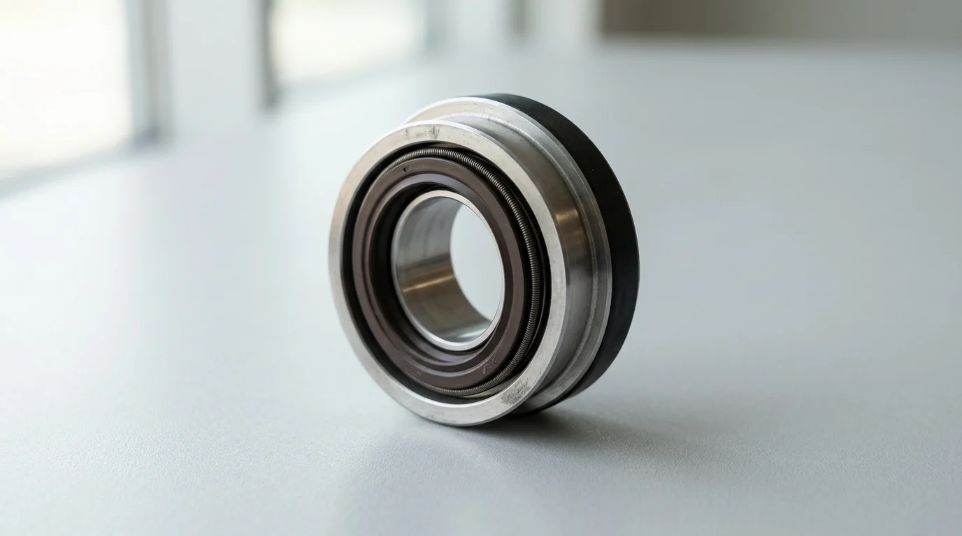
Pump Shaft Seal Basics and Main Types

Understanding the fundamental mechanics and available configurations of pump shaft seals is the first step in specifying the correct solution. The industry has evolved significantly from traditional compression packing to highly engineered mechanical seals designed for zero-emissions performance. Modern sealing solutions combine advanced metallurgy, precision-lapped faces, and engineered elastomers to manage extreme pressures, temperatures, and corrosive media.
Packing, single mechanical, double mechanical, and cartridge seals
Compression packing remains in use for highly abrasive slurries or non-critical water applications, but it requires controlled leakage—typically 40 to 60 drops per minute—to lubricate and cool the shaft. In contrast, mechanical seals provide virtually leak-free operation. Single mechanical seals utilize one set of precision-machined faces (one rotating, one stationary) lubricated by the pumped fluid. Double (dual) mechanical seals utilize two sets of faces and a barrier fluid, offering absolute containment for toxic or highly volatile media. Cartridge seals encapsulate the faces, springs, and elastomers into a single pre-assembled unit, eliminating the need for manual setting measurements and drastically reducing installation errors.
| Seal Configuration | Typical Leakage Rate | Maximum Pressure Limit | Primary Application Profile |
|---|---|---|---|
| Compression Packing | 40-60 drops/min | ~3.4 MPa (500 psi) | Slurries, large water transport, non-toxic media |
| Single Component Seal | < 5 ppm (vapor) | ~2.5 MPa (360 psi) | Standard water, light chemicals, intermittent duty |
| Single Cartridge Seal | < 5 ppm (vapor) | ~5.0 MPa (725 psi) | General continuous duty, standardized plant upgrades |
| Double Cartridge Seal | Zero process emissions | ~8.0 MPa (1,160 psi) | Toxic, hazardous, volatile, or crystallizing media |
Seal face materials, elastomers, and metallurgy
The longevity of a mechanical seal is heavily dependent on the materials selected for the primary seal faces. Common combinations include Carbon Graphite running against Silicon Carbide (SiC) or Tungsten Carbide (WC). SiC provides excellent thermal conductivity and extreme hardness, making it ideal for continuous duty, while Carbon offers superior self-lubricating properties during transient dry-run conditions. For highly abrasive environments, a hard-on-hard face combination (SiC vs. SiC) is required to prevent scoring.
Secondary sealing elements, specifically the elastomeric O-rings, must be chemically compatible with the pumped media and capable of withstanding operational temperatures. Standard Nitrile (NBR) or EPDM elastomers are suitable for ambient water applications, but aggressive chemical processing demands Fluoroelastomers (FKM) or Perfluoroelastomers (FFKM). Premium FFKM compounds can maintain elasticity and chemical resistance at continuous operating temperatures up to 320°C (608°F), ensuring the seal assembly remains dynamically responsive over years of operation.
How to Compare Seal Options
Comparing seal options requires a rigorous engineering analysis of the application’s operating parameters. Engineers must evaluate competing technologies based on thermodynamic limits, mechanical tolerances, and the total energy footprint of the sealing system. A holistic comparison ensures the selected seal will not only survive the application but operate efficiently without demanding excessive maintenance interventions.
Key technical selection criteria
The primary technical metric for comparing mechanical seals is the Pressure-Velocity (PV) limit. The PV value represents the product of the pressure drop across the seal face and the sliding velocity of the rotating face. Unbalanced mechanical seals are typically limited to a PV value of roughly 1.8 MPa·m/s. For higher-energy applications, balanced mechanical seals are required. Balancing reduces the hydraulic closing force on the seal faces, allowing them to handle PV limits up to 8.3 MPa·m/s or higher without generating destructive levels of frictional heat.
In addition to PV limits, engineers must evaluate the seal’s capability to handle axial and radial shaft movement. Bellows seals—which utilize a welded metal bellows rather than dynamic O-rings to provide spring force—are highly effective in high-temperature applications because they eliminate the risk of elastomer hang-up. Comparing spring mechanisms (multiple coil springs vs. wave springs vs. metal bellows) is essential for matching the seal’s dynamic tracking ability to the equipment’s vibration profile.
Lifecycle cost, energy loss, and installation sensitivity
Lifecycle cost analysis frequently reveals that the initial purchase price of a seal represents less than 15% of its total operational cost. Energy consumption is a major differentiator; traditional compression packing exerts continuous friction on the shaft or sleeve, consuming up to 6 times more electrical power than an equivalent mechanical seal. Over a 10-year lifespan of a 200 kW pump, this frictional energy loss can equate to tens of thousands of dollars in wasted electricity.
Installation sensitivity also drives lifecycle costs. Component seals require the installer to manually set the spring compression, often requiring tolerances within +/- 0.5 mm. A slight miscalculation leads to immediate face distortion or inadequate closing force. Cartridge seals, while commanding a higher initial premium, mitigate this risk entirely. Their plug-and-play design ensures perfect factory-set alignment, reducing installation time by up to 70% and virtually eliminating early-life failures caused by human error.
When a seal support system or API plan is needed
A mechanical seal is only as reliable as the fluid film between its faces. When the pumped media is too hot, too abrasive, or lacks sufficient lubricity, a seal support system becomes mandatory. The American Petroleum Institute (API) 682 standard defines specific piping plans to manage the seal environment. For example, Plan 11 utilizes a simple bypass flush from the pump discharge to cool the seal chamber and remove vapor bubbles in clean fluids.
For hazardous or highly volatile fluids, a dual seal paired with an API Plan 53A is often the standard. Plan 53A supplies a clean, pressurized barrier fluid from an external reservoir to the space between the inner and outer seal faces. To ensure zero process leakage to the atmosphere, the barrier fluid must be maintained at a pressure of 1.5 to 2.0 bar (22 to 29 psi) above the maximum stuffing box pressure. Comparing seal options must therefore include the capital and maintenance costs of these necessary auxiliary systems.
How to Select the Best Seal for the Application
Executing a structured selection process guarantees that no critical variable is overlooked. The transition from theoretical comparison to final specification demands a methodical review of fluid rheology, equipment geometry, and site-specific operational goals. Tailoring the seal to the precise industrial environment is the ultimate key to maximizing continuous uptime.
Step-by-step seal selection process
The step-by-step selection process begins with defining the fluid state: its exact chemical composition, concentration, specific gravity, viscosity, and vapor pressure at the operating temperature. Next, engineers must calculate the dynamic conditions within the stuffing box, noting the maximum discharge pressure and any potential vacuum conditions during startup. This data determines whether an unbalanced or balanced seal design is required.
The third step is selecting the seal arrangement (single, dual unpressurized, or dual pressurized) based on toxicity and environmental emission regulations. Finally, material selection is finalized. This involves cross-referencing the fluid properties against chemical compatibility charts to specify the metallurgy of the hardware (e.g., 316 Stainless Steel, Alloy 20, or Hastelloy C), the face materials, and the secondary elastomers. Skipping or assuming data in any of these steps inevitably leads to premature seal degradation.
Differences across water, chemical processing, and other applications
Application environments dictate vastly different sealing strategies. In municipal water and wastewater transport, the primary threat is abrasive particulate matter. Seals in these applications typically employ hard-on-hard face combinations (SiC/SiC) and robust single-spring or elastomer bellows designs that resist clogging from suspended solids. Conversely, the pharmaceutical and food processing sectors prioritize sanitary designs with highly polished surfaces (often < 0.4 µm Ra) and FDA-compliant elastomers to prevent bacterial growth.
| Industry / Application | Primary Fluid Challenge | Recommended Seal Arrangement | Optimal Face Materials | API Plan / Support |
|---|---|---|---|---|
| Municipal Wastewater | High abrasives, sludge | Single Cartridge, robust spring | SiC vs. SiC | Plan 32 (Clean Flush) |
| Chemical Processing | High toxicity, corrosivity | Dual Pressurized Cartridge | SiC vs. Carbon or SiC | Plan 53A / 54 |
| Hydrocarbon Refining | High temperature, volatility | High-Temp Metal Bellows | Carbon vs. Tungsten Carbide | Plan 21 / 52 |
| Boiler Feed Water | High pressure, low lubricity | Balanced Single Cartridge | Carbon vs. SiC | Plan 23 (Cooler) |
Pump Shaft Seal Decision Framework
Establishing a standardized decision framework allows plant managers and reliability engineers to consistently source, evaluate, and implement optimal sealing solutions. A rigorous framework filters out inferior products and aligns procurement strategies with long-term engineering objectives, ensuring that short-term budget constraints do not compromise critical plant infrastructure.
Warning signs of low-cost seal choices
Identifying the warning signs of low-cost, commoditized seals is crucial for protecting long-running equipment. Budget seals often compromise on the precision of face lapping. For a mechanical seal to function correctly, the primary faces must be lapped to a flatness of 2 to 3 helium light bands, which translates to a microscopic tolerance of 0.58 to 0.87 micrometers. Substandard lapping results in macro-leakage and rapid face wear within the first few weeks of operation.
Another red flag is the use of unbranded or generic elastomers. While a generic FKM O-ring may look identical to a premium, chemically certified equivalent, its formulation may lack the cross-linking density required to resist explosive decompression or high-temperature chemical attack. Furthermore, low-cost suppliers often utilize stamped metal components rather than precision-machined hardware, leading to uneven spring loading and distortion of the seal faces under high pressure.
Balancing standardization and supplier capability
A successful decision framework balances the desire for plant-wide standardization with the need for specialized supplier capabilities.
Key Takeaways
- The most important conclusions and rationale for pump shaft seal
- Specs, compliance, and risk checks worth validating before you commit
- Practical next steps and caveats readers can apply immediately
Frequently Asked Questions
What pump shaft seal is best for long-running equipment?
For most 24/7 industrial pumps, a cartridge mechanical seal is the best choice because it reduces installation errors, controls leakage, and supports longer service life.
When should I choose a double mechanical seal instead of a single seal?
Use a double seal for toxic, volatile, crystallizing, or hazardous media. It provides better containment and helps meet strict leakage and safety requirements.
Why are cartridge seals preferred for continuous-duty pumps?
Cartridge seals come pre-assembled and preset, so installation is faster and more accurate. This lowers startup mistakes and improves uptime on long-running equipment.
Which seal materials work best for harsh pump applications?
Silicon carbide or tungsten carbide faces are common for demanding service. Match elastomers and metal parts to temperature, pressure, and chemical compatibility for longer seal life.
Can Victor Seals supply OEM-compatible pump shaft seals for major brands?
Yes. Victor Seals provides replacement and OEM-compatible seals for brands like Grundfos, Flygt, IMO, Alfa Laval, APV, Lowara, Fristam, and Allweiler.

Post time: Jun-22-2026