


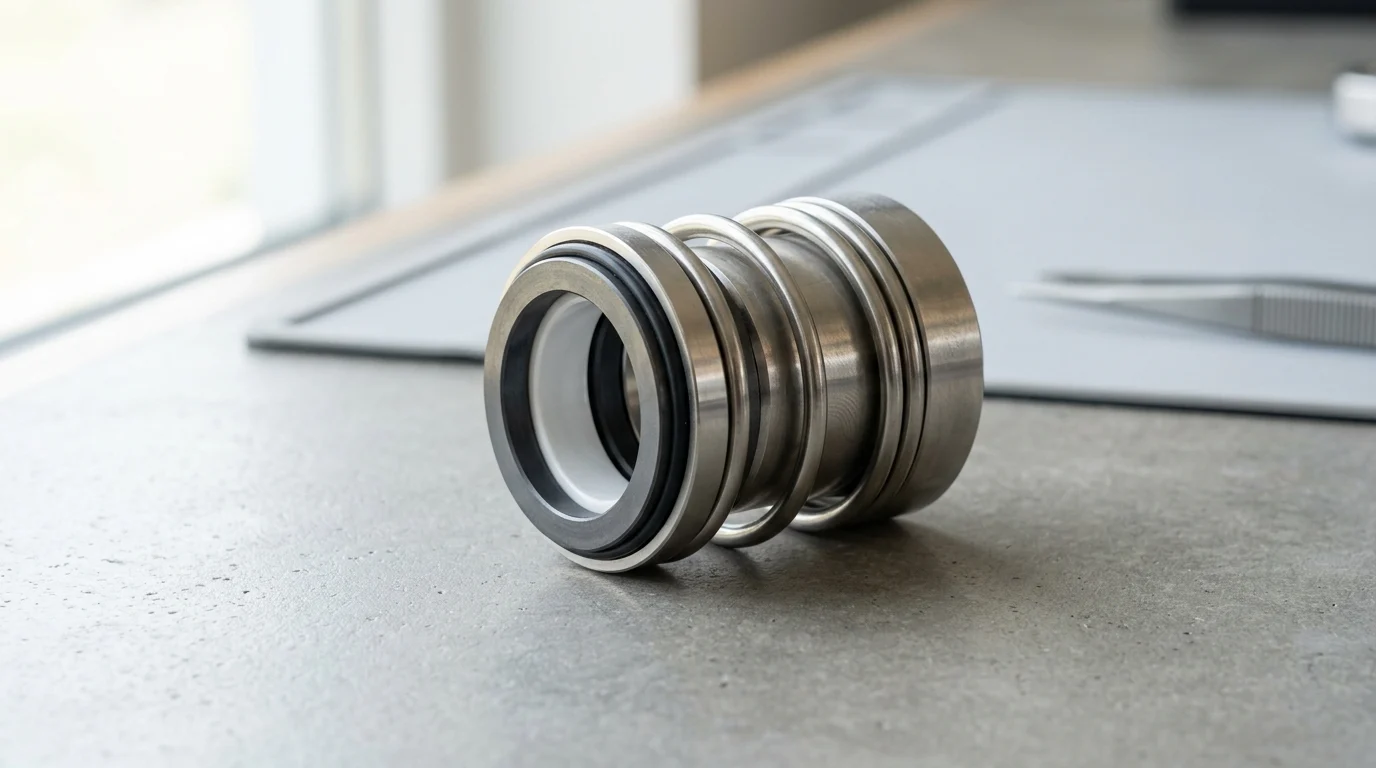
Why Installation Mistakes Cause Single Spring Mechanical Seal Leakage
Single spring mechanical seals are widely utilized across industrial fluid handling systems due to their robust construction, resistance to clogging, and ability to accommodate moderate shaft misalignment. Unlike multi-spring configurations, which use several smaller springs distributed around the seal face, the single spring design relies on one heavy-duty helical coil to provide the necessary closing force. While this simplicity offers distinct advantages in highly viscous or particulate-laden media, it also introduces specific vulnerabilities during the assembly and installation process.
The integrity of a mechanical seal fundamentally depends on maintaining a microscopic tribological film between the rotating and stationary faces. When installation procedures deviate from strict engineering tolerances, this delicate equilibrium is disrupted. Such disruptions manifest as premature wear, thermal degradation, and ultimately, fluid leakage. Understanding the precise mechanical and hydrodynamic reasons why installation errors translate directly into seal failure is the first step toward extending the mean time between failures (MTBF) for critical pumping assets.
How to Define Seal Leakage
To accurately diagnose installation-related failures, operators must first distinguish between normal operational weeping and catastrophic leakage. By design, mechanical seals are not entirely leak-free; they require a minute amount of fluid to migrate across the seal faces to provide lubrication and cooling. In optimal conditions, this fluid vaporizes upon reaching the atmospheric side, leaving no visible trace. The fluid film thickness typically ranges from 1 to 3 micrometers, depending on the fluid’s viscosity and the seal’s closing force.
Unacceptable leakage occurs when the fluid film breaks down or the faces separate, allowing liquid to pass through in measurable quantities. Industry standards generally define acceptable visible leakage for a healthy single spring seal as less than 3 to 5 drops per minute (approximately 0.15 to 0.25 milliliters per minute) per inch of shaft diameter. When leakage exceeds 10 drops per minute immediately after installation, it is a definitive indicator of an assembly error, face distortion, or an compromised secondary elastomeric seal.
Why Single Spring Seals Are Installation-Sensitive
The architecture of single spring seals makes them uniquely sensitive to installation precision. The heavy-duty coil spring not only provides the axial closing force but often transmits torque from the shaft to the rotating seal face. Because the spring is manufactured from thick wire, its compression characteristics are less forgiving than those of multi-spring designs. If the seal is not positioned exactly at the manufacturer’s specified working length, the spring will either exert excessive face pressure or fail to keep the faces closed during minor pressure fluctuations.
Furthermore, single spring seals are inherently directional. The helical coil must be wound in a direction that tightens based on the shaft’s rotation. Installing a right-hand wound spring on a pump shaft that rotates counter-clockwise (or vice versa) will cause the spring to unwind, expand in diameter, and lose its driving grip, leading to immediate face separation and massive leakage. This requirement demands meticulous attention to equipment documentation and rotational markings prior to assembly.
Pre-Installation Errors That Increase Leakage Risk

The groundwork for a successful mechanical seal installation is laid long before the seal is physically mounted onto the shaft. Pre-installation oversights—ranging from incorrect material specification to ignoring degraded pump hardware—guarantee premature leakage regardless of how carefully the assembly steps are executed. Maintenance teams must treat the pump shaft and seal chamber as precision environments, verifying every dimensional tolerance against original equipment manufacturer (OEM) specifications.
Incorrect Seal Selection and Elastomer Compatibility
Selecting the correct seal face materials and secondary elastomers is non-negotiable. A frequent pre-installation error is utilizing a seal with elastomers that are chemically incompatible with the process fluid or incapable of withstanding the operating temperatures. For example, Ethylene Propylene Diene Monomer (EPDM) O-rings offer excellent resistance to hot water and steam up to 150°C but will rapidly swell and disintegrate if exposed to petroleum-based oils. Conversely, Fluoroelastomers (FKM) handle oils flawlessly but degrade in hot amines or steam above 200°C.
When an incompatible elastomer is installed, it either swells, causing the rotating face to bind on the shaft (hang-up), or shrinks and hardens, resulting in an immediate secondary leakage path. Maintenance personnel must cross-reference the fluid’s chemical composition, maximum operating temperature, and cleaning-in-place (CIP) chemicals with the seal’s bill of materials prior to unboxing the unit.
Shaft, Sleeve, Bore, and Runout Problems
A mechanical seal cannot compensate for degraded pump hardware. The single spring design requires a stable rotational axis to maintain the 1 to 3 micrometer fluid film. Excessive shaft runout, deflection, or axial end play will dynamically force the seal faces apart with every revolution. Total Indicator Reading (TIR) for radial shaft runout must not exceed 0.002 inches (0.05 mm) at the seal face location. If the shaft is bent or the bearings are worn beyond this threshold, the heavy single spring will be forced to rapidly compress and expand, leading to fatigue and face tracking errors.
Similarly, the surface finish of the shaft or sleeve where the secondary O-ring seals must be pristine. The industry standard requires a surface roughness (Ra) between 16 and 32 micro-inches (0.4 to 0.8 micrometers). Scratches, fretting corrosion, or pitting deeper than 0.005 inches (0.127 mm) will provide a direct micro-channel for fluid to bypass the elastomer. Axial end play must also be strictly limited to a maximum of 0.003 inches (0.076 mm) to prevent the seal from operating outside its designed compression range.
Acceptable vs Risky Installation Conditions
To systematically evaluate whether a pump is ready for seal installation, reliability engineers utilize comparative threshold matrices. Proceeding with installation when conditions fall into the ‘Risky’ category dramatically increases the probability of infant mortality for the mechanical seal.
| Parameter | Acceptable Condition | Risky/Unacceptable Condition |
|---|---|---|
| Radial Shaft Runout (TIR) | < 0.05 mm (0.002 in) | > 0.05 mm (0.002 in) |
| Axial End Play | < 0.076 mm (0.003 in) | > 0.127 mm (0.005 in) |
| Shaft/Sleeve Surface Finish | 0.4 to 0.8 µm Ra (16-32 µin) | > 0.8 µm Ra or visible pitting |
| Seal Chamber Concentricity | < 0.127 mm (0.005 in) TIR | > 0.127 mm (0.005 in) TIR |
| Bearing Housing Vibration | < 2.5 mm/s (0.1 in/s) RMS | > 4.5 mm/s (0.18 in/s) RMS |
Adhering to these quantitative baselines ensures that the mechanical seal operates in an environment conducive to long-term reliability. Bypassing these checks in an effort to expedite a repair invariably results in repeat failures and elevated maintenance costs.
Assembly Mistakes During Seal Installation
The physical mounting of a single spring mechanical seal is a process that requires surgical cleanliness and exact geometric alignment. Unlike cartridge seals—which are pre-assembled and preset at the factory—component single spring seals must be manually positioned, compressed, and secured by the technician on the pump shaft. This manual intervention introduces several critical failure points where minor deviations can permanently damage the sealing interfaces.
Face Contamination and Chipped Seal Faces
The most highly engineered components of any mechanical seal are the primary rotating and stationary faces. These surfaces are typically manufactured from carbon graphite, silicon carbide, or tungsten carbide, and are lapped to an optical flatness of 1 to 2 light bands (0.3 to 0.6 micrometers). Because this tolerance is so minute, any particulate contamination—even an oily fingerprint, a speck of dust, or lint from a cleaning rag—can create a wedge that forces the faces apart.
Furthermore, these hard materials are exceptionally brittle. A common installation error involves striking the seal face against the shaft shoulder or the stuffing box wall during insertion. A micro-chip on the inner or outer diameter of the seal face disrupts the hydrodynamic fluid film, causing localized heat buildup, blistering, and rapid leakage. Technicians must handle seal faces exclusively by their outer edges and use alcohol-based solvents and lint-free optical wipes for final cleaning immediately prior to closing the pump casing.
Incorrect Spring Compression and Working Length
Because single spring seals are installed as separate components, establishing the correct working length (often referred to as the L1 dimension) is entirely dependent on the installer. The working length dictates the exact amount of spring compression required to generate the optimal specific face pressure. If the seal is set too far back on the shaft, the spring is under-compressed. In this state, a minor drop in system pressure or a slight axial shaft movement will cause the faces to separate, resulting in a sudden, high-volume leak.
Conversely, over-compressing the spring by setting the seal too far forward generates excessive mechanical force against the faces. A single spring seal typically operates with a face load of 15 to 30 psi (1.0 to 2.0 bar). Over-compression can easily double this load, squeezing out the lubricating fluid film and causing dry friction. This leads to extreme thermal shock, heat-checking (microscopic radial cracks on the hard face), and the destruction of the secondary elastomers due to conducted heat. The tolerance for setting the working length is generally strict, requiring accuracy within ±0.020 inches (0.5 mm) of the OEM specification.
Gland Misalignment and Uneven Bolt Tightening
The stationary face of the mechanical seal is held in place by the gland plate, which is secured to the pump casing via studs and nuts. A critical, yet frequently mishandled, step is the tightening of these gland fasteners. If the bolts are tightened unevenly or in a circular sequence rather than a crisscross (star) pattern, the gland plate will warp. This distortion transfers directly to the stationary seal face.
When the stationary face is distorted out of its sub-micrometer flatness, the rotating face cannot conform to the irregular surface, creating gaps that leak continuously. To prevent this, gland bolts must be tightened incrementally. For standard ANSI/API pumps, a torque wrench should be used to apply the final load, typically ranging from 15 to 25 Nm depending on the stud diameter and gasket material. Utilizing a feeler gauge between the gland plate and the stuffing box face ensures the gap is uniform within 0.005 inches (0.127 mm) across a full 360-degree sweep.
Commissioning and Operating Mistakes After Installation
A flawlessly executed mechanical seal installation can be entirely undone within the first 60 seconds of pump operation if strict commissioning protocols are ignored. The transition from a static, newly assembled state to dynamic operation introduces hydraulic and thermal forces that the seal must accommodate. Operating mistakes during this critical window account for a significant percentage of early-life single spring seal failures.
Dry Running, Poor Venting, and Inadequate Priming
The most destructive operating mistake following an installation is starting the pump without properly venting the seal chamber. Mechanical seals rely on the pumped fluid to dissipate the heat generated by face friction. If the pump casing and seal chamber are not fully primed and vented, a pocket of air or vapor will become trapped at the highest point of the stuffing box, leaving the seal faces running dry.
Without liquid lubrication, the temperature at the tribological interface can spike by over 150°C within 30 to 60 seconds. This rapid localized heating causes the fluid trapped in the micro-pores of carbon faces to expand explosively, a phenomenon known as blistering. In silicon carbide faces, the thermal shock leads to severe heat-checking and catastrophic shattering. Operators must manually open casing vents and seal flush lines to bleed all trapped air until a steady stream of liquid is observed before energizing the motor.
Pressure Spikes, Thermal Shock, and Vibration
System hydraulics play a pivotal role in seal longevity post-installation. Operating a pump outside of its Preferred Operating Region (POR)—typically defined as 70% to 120% of its Best Efficiency Point (BEP)—induces severe pressure fluctuations and shaft deflection. If an operator throttles the suction valve or allows the system to cavitate, the resulting pressure spikes can collapse the single spring or momentarily blow the seal faces open.
Cavitation also introduces high-frequency vibrations. While single spring seals are rugged, sustained vibration exceeding 0.25 inches per second (6.35 mm/s) RMS velocity will accelerate the wear of the drive pins and the spring itself. Additionally, introducing a fluid that is significantly hotter or colder than the ambient temperature of the pump without a gradual warm-up or cool-down period induces thermal shock. The differential expansion between the metal shaft, the elastomeric secondary seals, and the brittle seal faces can cause the rotating assembly to bind, leading to immediate leakage upon startup.
How Maintenance Teams Can Prevent Seal Leakage
Transitioning from reactive firefighting to proactive reliability requires maintenance teams to standardize their mechanical seal installation and troubleshooting procedures. By implementing rigorous quality control measures, technical training, and data-driven replacement strategies, facilities can drastically reduce the incidence of premature seal leakage. Upgrading standard operating procedures ensures that the precision required by the mechanical seal is matched by the execution of the maintenance personnel.
Step-by-Step Installation Checklist
A standardized installation checklist eliminates the variability inherent in manual assembly. First, technicians must perform a comprehensive dimensional audit, recording shaft runout, end play, and concentricity using dial indicators to ensure they fall within the sub-millimeter tolerances required. Second, all sharp edges, keyways, and threads over which the seal must pass should be covered with an assembly sleeve or taped to prevent slicing the secondary O-rings.
Third, lubricants applied to elastomers must be strictly verified for compatibility; for instance, using a silicone-based grease on EPDM O-rings, while strictly avoiding petroleum-based oils. Fourth, the exact working length must be scribed onto the shaft, and the single spring’s rotational direction must be confirmed against the pump’s rotational arrow. Finally, the gland plate torque sequence must be executed with a calibrated torque wrench, documenting the final torque values in the computerized maintenance management system (CMMS) for future auditing.
Troubleshooting and Replacement Decision Matrix
When a newly installed single spring seal leaks, maintenance teams must utilize a systematic decision matrix rather than immediately replacing the seal without identifying the root cause. Analyzing the failed components provides forensic evidence of the installation or operational error.
| Failure Symptom | Probable Root Cause | Corrective Action/Decision |
|---|---|---|
| Deep groove carved into pump shaft/sleeve | Elastomer hang-up or chemical swelling | Upgrade elastomer material; verify shaft surface finish is < 0.8 µm Ra. |
| Radial micro-cracks (heat-checking) on hard face | Dry running or excessive spring over-compression | Verify L1 working length dimension; implement mandatory venting/priming checklist. |
| Spring unwound or distorted | Incorrect spring direction installed | Match spring helix direction to shaft rotation (e.g., right-hand spring for CW rotation). |
| Uneven wear track on stationary face | Gland plate distortion / uneven bolt torque | Mandate star-pattern tightening sequence using a torque wrench calibrated annually. |
| Heavy chipping on outer diameter of seal face | Mechanical impact during installation | Implement specialized handling tools; mandate optical wipe cleaning protocol. |
By utilizing this matrix, maintenance teams can accurately pinpoint whether a failure was caused by a dimensional mismatch, an assembly oversight, or a systemic hydraulic issue. Correcting the underlying root cause rather than merely treating the symptom has been shown to improve mechanical seal MTBF from an industry average of 12 months to over 36 months, delivering substantial reductions in lifecycle costs and operational downtime.
Key Takeaways
- Confirm that visible leakage stays below about 3 to 5 drops per minute per inch of shaft diameter during normal operation.
- Treat leakage above 10 drops per minute immediately after installation as a likely sign of assembly error, face distortion, or elastomer damage.
- Set the seal to the manufacturer’s specified working length because over-compression increases heat while under-compression allows face separation.
- Verify shaft rotation and spring hand before assembly, since the wrong winding direction can cause the spring to unwind and lose torque transmission.
- Protect the 1 to 3 micrometer lubricating film between the seal faces by keeping the faces clean, aligned, and correctly loaded.
Frequently Asked Questions
Is any leakage normal in a single spring mechanical seal?
Yes. A microscopic fluid film lubricates and cools the seal faces. In good conditions, it usually vaporizes and is not visibly noticeable.
How much leakage is considered acceptable after installation?
A healthy seal is often expected to stay below about 3 to 5 drops per minute per inch of shaft diameter, depending on service conditions.
What does leakage above 10 drops per minute indicate?
Leakage above 10 drops per minute immediately after installation usually points to an assembly error, distorted seal faces, or a damaged secondary elastomer.
Why is spring direction important on a single spring seal?
The coil must tighten in the shaft’s rotation direction. If installed with the wrong hand of spring, it can unwind, lose grip, and allow face separation.
Why does incorrect working length cause leakage?
If the seal is compressed too much, face pressure and heat increase. If compressed too little, the faces may not stay closed during pressure changes.

Post time: Oct-18-2026