


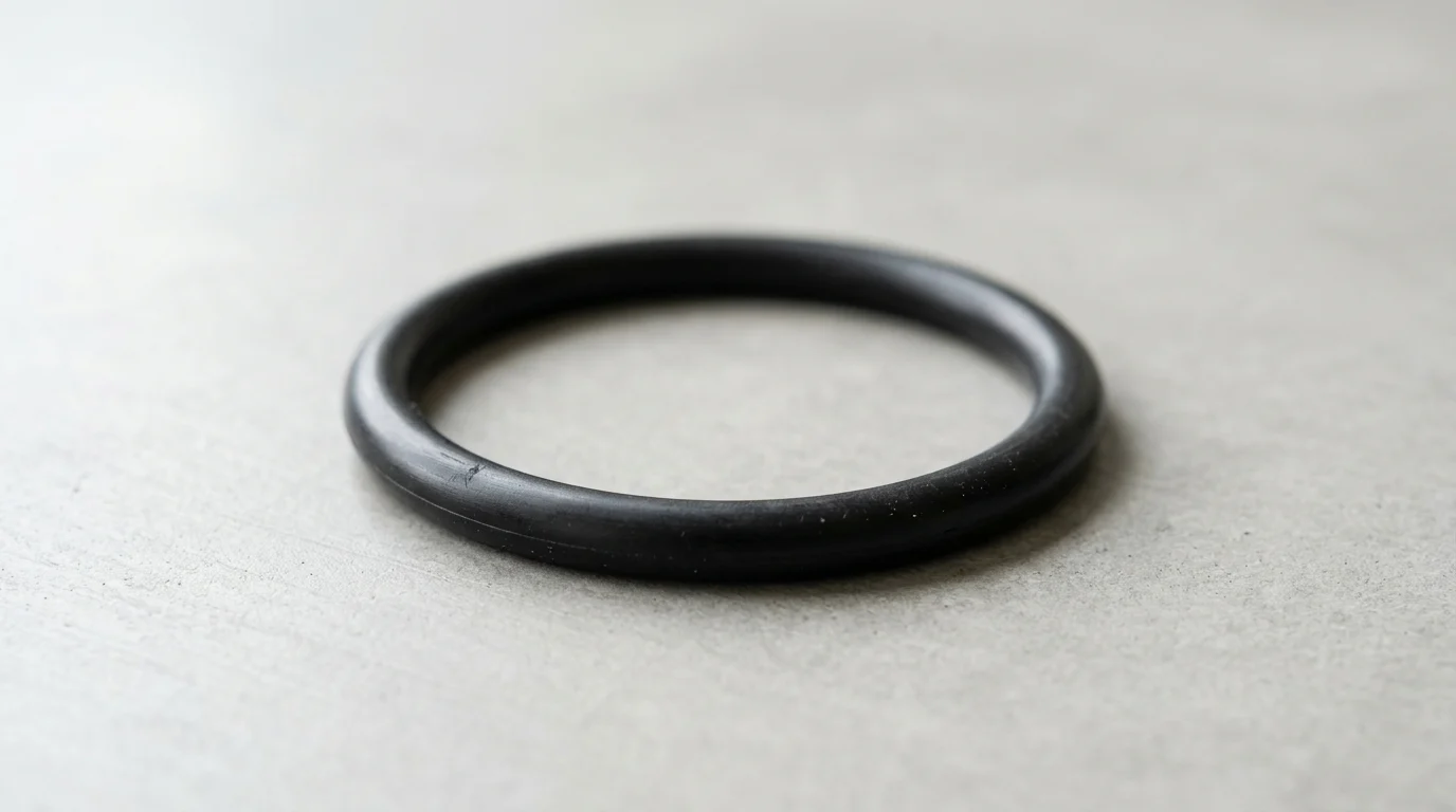
Why O-Ring Installation Quality Matters in Centrifugal Pumps
Centrifugal pumps operate under demanding hydrodynamic conditions, relying heavily on the integrity of elastomeric boundaries to prevent fluid leaks and maintain internal pressure gradients. The fundamental reliability of these systems often hinges on a single, seemingly simple component: the O-ring seal. Despite their ubiquitous presence and straightforward geometry, the effectiveness of these seals is highly sensitive to installation quality.
Microscopic deviations during the assembly phase can compromise the elastomer’s memory and sealing footprint, leading to premature failure. Industrial operators consistently find that mechanical seal failures represent the largest single category of pump maintenance events, with improper installation of static and secondary dynamic O-rings accounting for a substantial percentage of these incidents.
Role of O-Rings in Pump Sealing
The primary function of an O-ring seal in a centrifugal pump is to block the clearance gap between two mating hardware surfaces, creating a barrier that is impermeable to the process fluid. This is achieved through mechanical deformation, commonly referred to as squeeze. In standard centrifugal pump applications, static seals require a cross-sectional squeeze between 15% and 30%, while secondary dynamic seals—such as those found sliding along a mechanical seal shaft sleeve—demand a lower squeeze of 8% to 16% to minimize friction and wear.
When system pressure is applied, the O-ring is driven toward the low-pressure side of the gland, deforming further to plug the diametral clearance. If the initial installation fails to establish the correct baseline squeeze due to improper seating or twisting, the fluid pressure will bypass the elastomer entirely, resulting in immediate leakage upon pump startup.
Leakage, Downtime, and Warranty Risks
The consequences of a compromised O-ring seal extend far beyond the negligible cost of the elastomer itself. A typical industrial O-ring may cost between $2 and $15, yet its failure can trigger cascading financial and operational losses. In continuous process industries, such as hydrocarbon refining or power generation, a single pump failure can result in downtime costs exceeding $25,000 per hour depending on process criticality.
Furthermore, environmental regulations impose strict penalties for the uncontained release of hazardous fluids, adding compliance risks to the operational burden. Warranty claims submitted to pump manufacturers are frequently contested and rejected when forensic teardowns reveal clear evidence of installation errors, such as pinched cross-sections or spiral failures, shifting the entire financial liability back to the plant operator.
Common Locations for Installation Defects
Within the architecture of a centrifugal pump, O-ring seals are deployed at several critical junctions, each presenting unique installation challenges. The casing or volute gasket is a primary static seal that spans a large diameter; installation defects here often involve the O-ring falling out of its groove or getting pinched during the torquing of the casing bolts.
Mechanical seal glands utilize O-rings to seal the stationary gland plate to the pump casing, where diametral clearances exceeding 0.005 inches can lead to extrusion if the O-ring is not perfectly aligned. Additionally, shaft sleeves and impeller nuts utilize smaller internal O-rings that are highly susceptible to being cut by shaft threads, splines, or keyways as they are slid into position during rotor assembly without proper protective sleeves.
Common Installation Errors That Cause O-Ring Leakage
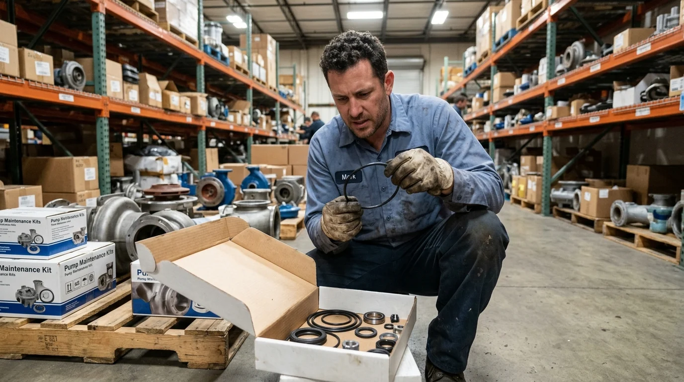
Even when the correct materials are specified for a centrifugal pump application, human error during the assembly process can instantly compromise the sealing system. Installation errors typically manifest as physical deformations or structural damage to the elastomer, preventing it from forming a continuous barrier against process fluids.
Understanding the specific mechanisms of these installation errors is critical for maintenance personnel to adjust their assembly techniques and prevent recurring leakage issues.
Incorrect Sizing, Stretch, and Squeeze
One of the most frequent errors is forcing an improperly sized O-ring into a gland, altering its engineered cross-section diameter (CSD). When an O-ring inside diameter (ID) is stretched too far over a pump shaft or sleeve, the cross-section undergoes a corresponding reduction in thickness. Industry standards dictate that an O-ring should ideally be stretched no more than 1% to 3% of its resting ID, with an absolute maximum threshold of 5%.
Exceeding this 5% stretch limit reduces the CSD to a point where the required 15% to 30% static squeeze is no longer achieved. Conversely, if an O-ring is too large and forced into a bore, it will buckle or wrinkle, creating built-in leak paths. Proper sizing requires verifying both the ID and the CSD with precision calipers before attempting installation.
Twisting, Rolling, Pinching, and Extrusion
Dynamic and semi-dynamic O-rings, such as those in mechanical seal pusher assemblies, are highly vulnerable to twisting and rolling during installation. If an O-ring is rolled down a shaft rather than being properly lubricated and slid into place, the elastomer develops internal torsional stress. During pump operation, this stress causes the seal to spiral and eventually tear—a phenomenon known as spiral failure.
Pinching occurs when an O-ring slips out of its groove just as mating metal parts, like the pump casing and cover, are bolted together. This severs or deeply gouges the elastomer. Furthermore, if the O-ring is improperly seated in an oversized clearance gap, high system pressure (e.g., exceeding 1,500 psi without backup rings) will force the elastomer into the gap, causing extrusion and nibbling that systematically destroys the seal edge.
Surface Damage, Contamination, and Misalignment
The condition of the metal sealing surfaces is just as critical as the handling of the O-ring itself. Installing an O-ring over dirty, burred, or improperly finished surfaces guarantees failure. Particulate contamination larger than 50 microns can become trapped between the elastomer and the metal, creating a micro-channel for fluid to bypass the seal.
Installation tools also play a destructive role; mechanics using flathead screwdrivers or sharp picks to stretch O-rings over threads frequently inflict micro-tears that propagate under pressure. Additionally, the surface finish of the hardware must meet specific parameters: dynamic sealing surfaces typically require a finish of 16 to 32 micro-inches Ra, while static surfaces can tolerate 32 to 63 micro-inches Ra. Installing a seal onto a surface that is too rough will abrade the elastomer, while a surface that is too smooth may prevent the retention of necessary lubricants.
Material and Lubrication Factors That Affect Seal Performance
The physical mechanics of O-ring installation cannot be divorced from the material science governing the elastomers and the lubricants used during assembly. An otherwise flawless mechanical installation will still result in catastrophic leakage if the seal material or the assembly lubricant is chemically incompatible with the pump’s operating environment.
Selecting the correct elastomer and pairing it with a compatible, non-destructive lubricant is a prerequisite for long-term sealing reliability.
Elastomer Compatibility with Fluids and Temperatures
Elastomers react dynamically to the chemical composition of the process fluid and the thermal load of the pump. Chemical incompatibility typically manifests as either severe embrittlement or excessive volume swell. While a minor volume swell of up to 10% can sometimes improve sealing by increasing squeeze, a swell exceeding 15% to 20% will cause the O-ring to overfill the gland.
Once the gland volume exceeds 100% capacity, the elastomer extrudes out of the clearance gaps, leading to rapid degradation and leakage. Temperature limits are equally rigid; operating an elastomer below its glass transition temperature causes it to lose flexibility and fail to track dynamic movements, while exceeding its upper thermal limit accelerates compression set, permanently flattening the O-ring.
Lubricant Selection and Swelling Risks
Lubrication is essential during installation to reduce friction, prevent tearing over threads, and allow the O-ring to seat evenly without twisting. However, introducing the wrong lubricant can destroy the seal before the pump is even commissioned. The cardinal rule of O-ring lubrication is that the lubricant must not share the same chemical base as the elastomer.
For example, applying a petroleum-based hydrocarbon grease to a standard EPDM (Ethylene Propylene Diene Monomer) O-ring will induce a massive chemical reaction, often resulting in a volume swell exceeding 50% within a matter of hours. To mitigate these risks, operators typically rely on inert silicone greases, barium-based lubricants, or PTFE-based fluids, provided they have cross-referenced the specific elastomer compatibility charts.
Comparison of Common O-Ring Materials
Pump operators must navigate a complex matrix of material options, balancing cost, thermal resilience, and chemical resistance. Standardizing on a single material for an entire plant is rarely feasible due to the diverse nature of process fluids.
The table below outlines the operational thresholds and typical applications for the most common elastomeric O-ring materials used in centrifugal pumps, providing a baseline for correct specification prior to installation.
| Elastomer Material | Common Trade Name | Max Temp Range (°C) | Volume Swell Risk Profile | Typical Pump Applications |
|---|---|---|---|---|
| NBR (Nitrile) | Buna-N | -30°C to +120°C | High risk with ozone/ketones | Water, general oils, mild chemicals |
| FKM (Fluorocarbon) | Viton™ | -20°C to +200°C | High risk with hot water/steam | Hydrocarbons, acids, high-temp fluids |
| EPDM | N/A | -40°C to +150°C | Extreme risk with petroleum | Hot water, steam, alkaline solutions |
| FFKM (Perfluoroelastomer) | Kalrez® | -20°C to +327°C | Very low risk (highly inert) | Aggressive chemical processing, extreme heat |
Best Practices to Prevent O-Ring Leakage During Installation
Preventing O-ring leakage requires shifting the maintenance approach from reactive troubleshooting to proactive precision assembly. Implementing strict, repeatable best practices ensures that the elastomer achieves its engineered sealing geometry without sustaining damage during the critical assembly phase.
By controlling the variables of hardware inspection, installation sequencing, and torque application, facilities can drastically reduce the incidence of early failure in pump seals.
Inspecting Grooves, Chamfers, and Sealing Surfaces
Before an O-ring is even touched, the mating hardware must undergo rigorous inspection. The leading cause of installation damage is forcing the elastomer past sharp metal edges. Hardware designs should incorporate lead-in chamfers at a 15° to 20° angle to compress the O-ring gradually as it enters the bore.
Inspect all groove edges, shoulders, and transition points to ensure they are properly radiused, typically requiring a radius of 0.005 to 0.015 inches. Any burrs, machining marks, or sharp transitions must be polished out. Furthermore, the gland depth and width must be measured with a depth micrometer to confirm they meet the dimensional tolerances specified by the seal manufacturer, ensuring the calculated squeeze and gland fill percentages will be accurate.
Step-by-Step Installation Sequence
A standardized step-by-step installation sequence minimizes the introduction of human error. First, the O-ring and the hardware must be cleaned with a non-residue solvent to remove particulate matter. Next, apply a thin, uniform film of compatible lubricant to both the O-ring and the hardware lead-in chamfers.
When installing over a shaft, never push the O-ring directly over exposed threads, splines, or keyways. Instead, use an installation cone or a thin-walled Mylar sleeve to bridge the sharp features, allowing the O-ring to slide safely into its groove. Once in the groove, use a blunt, non-metallic tool—such as a brass or plastic pick—to ensure the seal is seated evenly and to relieve any accumulated torsional stress by gently running the tool around the circumference.
Torque, Alignment, and Cleanliness Checks
The final phase of installation involves the mechanical assembly of the pump components, which directly impacts the compression of the O-ring. When tightening casing bolts or gland plates, mechanics must use a calibrated torque wrench and follow a strict, alternating star pattern.
Uneven torque application can cause the metal flanges to cock, resulting in a localized gland compression variance of up to 40%. This pinches the O-ring on one side while leaving a critical lack of squeeze on the opposite side, creating an immediate leak path. Finally, a post-assembly cleanliness check should verify that no environmental debris, such as shop rags or grit, has been trapped in the flange gap, which would compromise the metal-to-metal contact required to enclose the O-ring gland fully.
When to Reinstall, Replace, or Escalate Pump Seal Issues
Even with stringent protocols, O-ring leakage can occasionally occur post-startup. The critical task for maintenance personnel is accurately diagnosing whether the failure stems from a flawed installation, normal operational wear, or a fundamental incompatibility with the system parameters.
Proper escalation of seal issues prevents the costly cycle of repeatedly replacing elastomers without addressing the root cause of the failure.
Identifying Installation Error Versus Seal Wear
Forensic analysis of a failed O-ring provides distinct clues to separate installation errors from operational wear. If an O-ring exhibits deep spiral cuts winding around its circumference, the root cause is almost exclusively an installation error where the seal was rolled rather than slid into place. Similarly, clean, sharp slices or localized gouges point to the O-ring being pushed past a sharp burr or an unchamfered edge during assembly.
Conversely, operational wear leaves different signatures. A seal that exhibits a permanent flat spot on its cross-section has suffered compression set. While a compression set exceeding 80% of the original squeeze is usually an indicator of excessive thermal or chemical exposure over time, an immediate flat spot combined with cracking upon initial startup suggests the O-ring was grossly oversized for the gland, resulting in extreme over-squeeze.
When O-Ring Replacement Is Not Enough
There are scenarios where the elastomer is not the limiting factor, and simply installing a new O-ring will not resolve the leakage. Hardware degradation is a primary reason for repeated seal failures. If the metal gland floor or sealing face exhibits corrosion pitting that is deeper than 0.002 inches, the elastomer cannot deform sufficiently to fill the micro-cavities, allowing fluid to bypass.
In such cases, the metal components must be remachined or replaced. Furthermore, if the system pressure or fluid volatility has been upgraded beyond the original pump specifications, standard O-ring seals may no longer be adequate. Operators must then escalate the solution by upgrading to engineered mechanical seals, installing backup rings to prevent extrusion, or changing the pump metallurgy to resist corrosion.
Leakage Symptom Decision Matrix
To streamline troubleshooting and prevent repetitive maintenance cycles, operators should utilize a structured decision matrix. This matrix maps the visual symptoms of the leaking O-ring directly to the most probable causes and dictates the appropriate corrective action.
| Visual Symptom on O-Ring | Probable Cause | Recommended Corrective Action |
|---|---|---|
| Deep spiral cuts / twisting | Rolled during installation | Use installation sleeves; apply proper lubricant; avoid rolling. |
| Missing chunks / nibbled edges | Extrusion due to high pressure or large clearance | Check hardware clearances; install backup rings if pressure >1,500 psi. |
| Clean slice or gouge | Pinched by hardware or cut by threads | Implement 15°-20° lead-in chamfers; use protective tape over threads. |
| Massive volume swell (>20%) | Chemical incompatibility (fluid or lube) | Cross-reference material charts; switch to inert assembly grease. |
| Permanent flat profile (Set) | Excessive heat or extreme over-squeeze | Verify CSD sizing with calipers; upgrade to high-temp elastomer (e.g., FFKM). |
Key Takeaways
- Verify that static O-rings have 15% to 30% squeeze and secondary dynamic O-rings have 8% to 16% squeeze before commissioning a centrifugal pump.
- Inspect every O-ring for twisting, pinching, cuts, and improper seating because small installation defects can cause immediate leakage at startup.
- Clean grooves, gland faces, shaft sleeves, and casing joints thoroughly before assembly to prevent debris from creating leak paths or damaging the elastomer.
- Pay special attention to large casing or volute O-rings, which can fall out of their grooves or become pinched during bolt tightening.
- Treat O-ring installation as a reliability-critical task because a low-cost seal failure can lead to costly downtime, environmental exposure, and rejected warranty claims.
Frequently Asked Questions
Why do O-rings leak after centrifugal pump installation?
Leaks often occur because the O-ring was twisted, pinched, cut, over-stretched, installed in a dirty groove, or seated with the wrong squeeze. Even small assembly errors can prevent the elastomer from filling the clearance gap under pressure.
What is the correct O-ring squeeze for pump seals?
Static O-rings in centrifugal pumps typically need 15% to 30% cross-sectional squeeze. Secondary dynamic O-rings, such as those moving on a mechanical seal sleeve, usually require 8% to 16% squeeze to reduce friction and wear.
Can a low-cost O-ring cause expensive pump downtime?
Yes. Although many industrial O-rings cost only a few dollars, failure can stop a critical pump and cause major downtime. In continuous processing plants, a single pump outage can cost tens of thousands of dollars per hour.
How does twisting damage an O-ring seal?
A twisted O-ring creates an uneven sealing footprint and may develop spiral failure during operation. This prevents uniform compression, allowing process fluid to bypass the seal or causing premature cracking and wear.
Why is groove cleanliness important during O-ring installation?
Dirt, metal chips, old elastomer fragments, or dried fluid in the groove can stop the O-ring from seating correctly. Contamination also creates leak paths and may cut or abrade the seal during pump assembly.

Post time: Oct-30-2026