


Why Mechanical Seal Reliability Is Strategic
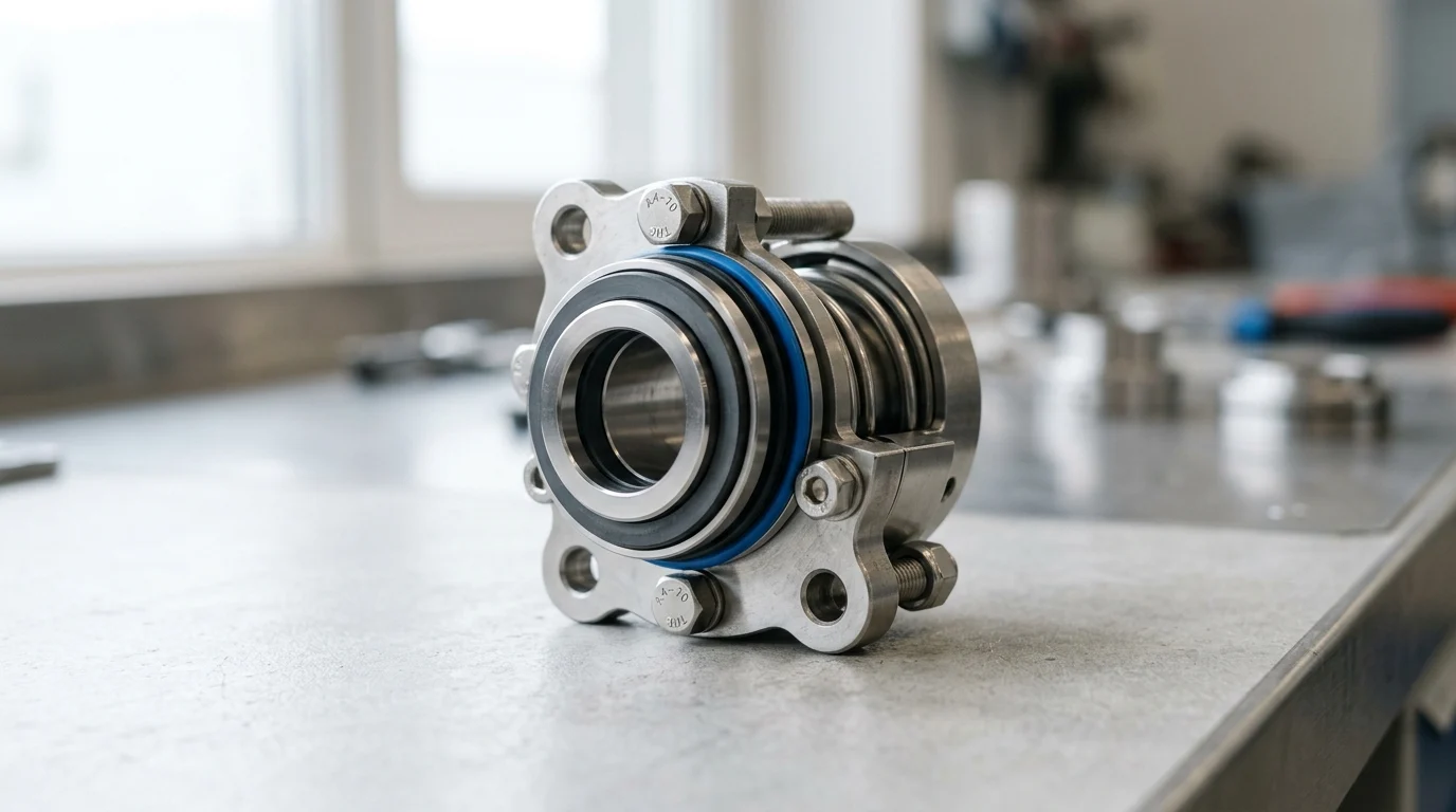
Modern desalination facilities, particularly Seawater Reverse Osmosis (SWRO) plants, rely entirely on the continuous operation of high-pressure pumps and energy recovery devices. Mechanical seals sit at the heart of these rotating assets, containing highly corrosive fluids under extreme dynamic conditions.
High-pressure feed pumps in a typical SWRO plant operate continuously at discharge pressures between 60 and 85 bar (870 to 1,230 psi). Seal reliability directly drives overall plant availability, energy efficiency, and maintenance expenditure. Recognizing the strategic importance of these components helps operators optimize lifecycle costs and maintain uninterrupted potable water production.
Impact of seal failures on uptime
Mechanical seal failures consistently rank among the top causes of unplanned pump outages in desalination environments. When a seal fails catastrophically on a primary high-pressure reverse osmosis feed pump, the resulting downtime can halt trains producing tens of millions of gallons per day (MGD)—equivalent to tens of thousands of cubic meters per day.
The financial impact is twofold: the direct cost of replacement components and the severe revenue loss from interrupted water production, which can represent a massive hourly financial penalty for large-scale municipal facilities. Consequently, plant operators frequently target Mean Time Between Failures (MTBF) benchmarks of 24,000 to 36,000 operating hours. These targets vary dramatically depending on the seal type, manufacturer quality tiers, and whether the metric refers to primary seal face wear or full cartridge replacement. While actual MTBF fluctuates based on application and operating conditions, establishing these baselines helps align maintenance with major pump overhaul cycles and prevents mid-cycle disruptions.
Seal risks in seawater intake systems
Seawater intake systems present distinct reliability risks because they operate upstream of fine filtration processes. Intake pumps, typically massive vertical turbine units, handle raw seawater laden with sand, silt, biological matter, and macro-debris.
Total Suspended Solids (TSS) in these environments frequently create a highly abrasive slurry. Without proper environmental controls, abrasive particles penetrate the fluid film between the seal faces, causing deep concentric grooving, accelerated wear, and eventual loss of containment. Mitigating these risks requires specialized seal geometries and robust flush plans designed to systematically exclude particulate matter from the pump’s stuffing box.
How to Define the Mechanical Seal Duty Envelope
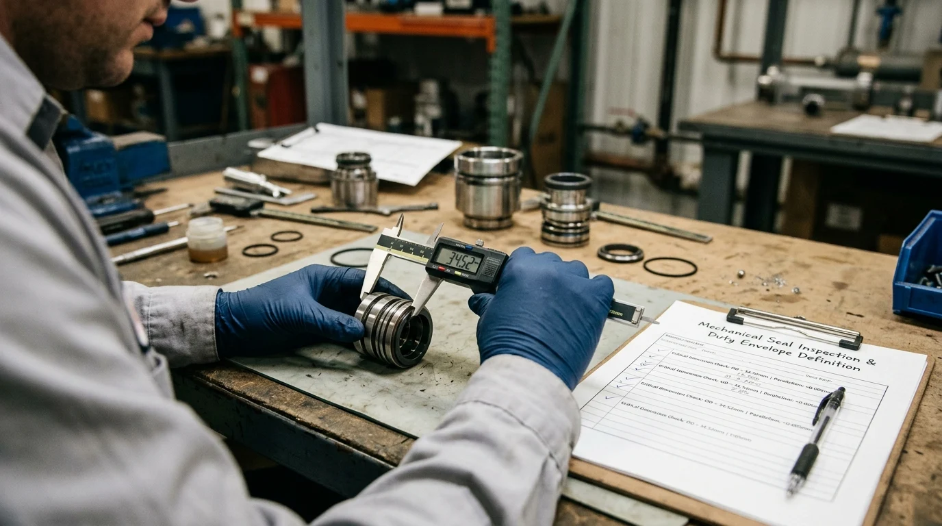
Accurately defining the mechanical seal duty envelope is the foundational step in mitigating premature failures and securing long-term operational stability. The duty envelope encompasses all physical, chemical, and thermal conditions the seal will encounter during steady-state operations and transient events, such as startup, shutdown, and process upsets.
Rigorous documentation of these parameters enables the selection of seal profiles that comply with stringent industry standards, such as API 682. However, because API 682 was primarily designed for hydrocarbon service, desalination plants must carefully adapt or supplement these guidelines to address the unique corrosivity and lack of lubricity inherent to water and seawater applications.
Operating parameters to document
Comprehensive documentation of operating parameters must extend beyond nominal design points to capture the full spectrum of operational realities. Critical metrics include stuffing box pressure, which fluctuates wildly during pump throttling, and shaft rotational speed, typically ranging from 1,500 to 3,600 RPM depending on the motor and drive configuration.
Additionally, the precise shaft or sleeve diameter—often ranging from 50 mm to 150 mm on large SWRO pumps—heavily influences the seal’s peripheral velocity and heat generation. System designers must also account for the fluid’s specific gravity and vapor pressure to ensure the seal faces maintain a stable, liquid lubricating film rather than operating in a detrimental dry-running or flashing regime.
Effects of salinity, solids, and temperature
The chemical and thermal composition of the pumped fluid imposes severe constraints on mechanical seal longevity. Raw seawater typically features a Total Dissolved Solids (TDS) concentration between 35,000 and 45,000 ppm, combined with high chloride levels that aggressively attack standard metallurgy.
This hyper-saline environment requires materials with a Pitting Resistance Equivalent Number (PREN) exceeding 40. Furthermore, regional thermal variability—from stable 15°C deep-water intakes to shallow intakes approaching 45°C—directly dictates seal material selection. Elevated temperatures accelerate corrosion rates, increase the risk of salt crystallization, and reduce the viscosity of the essential lubricating fluid film. Intake design—whether deep-water, shallow, or subsurface—establishes the baseline thermal and particulate load the seal must handle.
Key differences between balanced and unbalanced seals
The fundamental distinction between balanced and unbalanced mechanical seals determines their suitability across different pressure regimes within the desalination process. Unbalanced seals experience the full hydraulic force of the stuffing box pressure acting on the seal face area, leading to high face loading. Conversely, balanced seals feature a stepped shaft or sleeve design that reduces the hydraulic area, lowering the net closing force and minimizing heat generation.
| Feature | Unbalanced Mechanical Seals | Balanced Mechanical Seals |
|---|---|---|
| Pressure Limit | Typically limited to 10–12 bar (145–175 psi) | Capable of exceeding 80 bar (1,160 psi) |
| Face Heat Generation | High, increasing risk of fluid vaporization | Low to moderate, maintaining stable fluid film |
| Application in SWRO | Low-pressure transfer and chemical dosing | High-pressure feed, booster, and ERD pumps |
| Design Complexity | Simple, requiring a straight shaft/sleeve | Requires a stepped shaft or specialized sleeve |
High-pressure SWRO feed pumps require a balanced design. The excessive face loads of an unbalanced seal operating at 80 bar significantly elevate the risk of fluid vaporization, which can lead to severe dry-running and thermal damage to the seal faces. Balanced geometries are also mandatory for energy recovery device (ERD) seals. ERDs operate under highly distinct conditions compared to standard feed pumps, handling simultaneous high-pressure and low-pressure streams, rapid pressure transients, and bidirectional flow, making specialized balanced designs critical for maintaining stability.
Mechanical Seal Designs, Materials, and Support Systems
Successful deployment of a mechanical seal in a desalination plant relies on a synergistic combination of structural design, advanced metallurgy, specialized face materials, and an appropriately engineered environmental support system.
Because seawater and concentrated brine are inherently hostile, standard off-the-shelf industrial seals rarely suffice. Instead, plant engineers and seal manufacturers tailor every component of the seal assembly to withstand the specific abrasiveness, corrosivity, and pressure profile of the application.
Single, dual unpressurized, and pressurized seal options
The fluid’s hazard level and the pump’s operating conditions drive the choice between single, dual unpressurized, and dual pressurized seal configurations. Single seals serve as the standard for low-to-medium pressure water applications where minor atmospheric vapor leakage is acceptable and easily managed.
However, dual pressurized seals (historically referred to as double seals) are increasingly specified for high-pressure brine and critical feed pumps. In a dual pressurized setup, a barrier fluid is maintained at a pressure of 1.5 to 2.0 bar higher than the pump’s stuffing box pressure. This pressure differential guarantees that if the inboard seal face is compromised, the clean barrier fluid leaks into the process, rather than allowing highly corrosive, high-pressure brine to escape into the atmosphere or damage the outboard seal components. Dual unpressurized (tandem) seals offer a middle ground, utilizing a buffer fluid to capture leakage and prevent salt crystallization without requiring a high-pressure support system.
Face materials, elastomers, springs, and metal components
Material selection is arguably the most critical variable in mechanical seal specification for SWRO. For the primary sealing faces, Silicon Carbide (SiC) serves as the industry standard due to its exceptional hardness, high thermal conductivity, and near-universal chemical resistance. In highly abrasive intake applications, Tungsten Carbide (TC) may be paired with SiC for added toughness.
Elastomeric secondary seals (O-rings) must resist both chemical degradation and explosive decompression; Fluoroelastomers (FKM) or Perfluoroelastomers (FFKM) are highly recommended. Crucially, all wetted metal components—including the gland plate, drive collar, and coil springs—must utilize high-alloy metallurgy. Super Duplex Stainless Steels (such as UNS S32750) or Titanium are essential to prevent crevice corrosion and chloride-induced stress corrosion cracking, which can severely degrade standard 316 stainless steel. Depending on chloride concentration, temperature, and crevice geometry, 316 stainless steel may experience rapid pitting and failure within months in these aggressive environments.
Comparison of mechanical seal support plans
Even the most robust mechanical seal will fail prematurely if its operating environment is not strictly controlled by a mechanical seal support system, categorized by standardized API piping plans. These plans regulate the temperature, pressure, and cleanliness of the fluid interacting with the seal faces.
| API Piping Plan | Description | Primary Desalination Application | Key Advantage |
|---|---|---|---|
| Plan 11 | Recirculation from pump discharge through an orifice to the seal. | Clean water pumps, product water transfer. | Simple, cost-effective cooling and venting. |
| Plan 32 | Injection of clean, external flush fluid into the stuffing box. | Raw seawater intake pumps with high TSS. | Excludes abrasive solids from seal faces. |
| Plan 53B | Pressurized barrier fluid circulation using a bladder accumulator. | High-pressure SWRO feed pumps. | Reliable barrier pressure without gas entrainment. |
| Plan 54 | External pressurized barrier fluid system circulating to multiple seals. | Extremely high-pressure or critical multi-pump trains. | Superior cooling capacity and centralized monitoring. |
For instance, utilizing a Plan 32 flush on an intake pump requires a continuous supply of filtered water at a flow rate of 4 to 8 liters per minute. While this represents a parasitic loss of both treated water and the energy used to pump it—which must be factored into plant efficiency calculations—it remains indispensable for extending seal life in high-TSS environments. Conversely, a Plan 53B system provides reliable barrier pressure for high-pressure feed pumps without the parasitic fluid loss, though it requires careful accumulator maintenance.
How to Diagnose and Prevent Mechanical Seal Failure
Maximizing mechanical seal longevity requires a transition from reactive replacement to proactive diagnostics and rigorous installation protocols. While mechanical seals are ultimately consumable components, their failure trajectories provide invaluable data regarding broader pump health and process anomalies.
By identifying the root causes of degradation and implementing strict monitoring frameworks, desalination operators can intercept impending failures before they cascade into catastrophic pump damage or extended plant downtime.
Failure modes caused by abrasion, crystallization, and corrosion
Failure modes in desalination mechanical seals span several categories, including crystallization, corrosion, and biofouling. With abrasive wear from intake solids already addressed, other threats prove equally destructive.
Crystallization remains a pervasive threat in brine and high-salinity applications. When microscopic amounts of seawater leak across the seal faces and evaporate on the atmospheric side, they leave behind hard salt crystals. These crystals act as grinding compounds, rapidly destroying the softer carbon or SiC faces and leading to sudden, massive leakage. Corrosion takes multiple forms: crevice corrosion under O-rings compromises face tracking, while electrochemical corrosion from stray currents in the pump system can rapidly pit and degrade seal faces. Furthermore, biofouling-induced seal hang-up occurs when marine organisms or organic matter accumulate around the dynamic components, restricting spring movement and causing the seal to leak profusely as shaft dynamics shift.
Crucially, these failure modes are highly interdependent. For example, temperature spikes reduce fluid film thickness and enable rapid crystallization, while crevice corrosion creates uneven surfaces that accelerate abrasive wear. Recognizing these interconnected relationships significantly improves diagnostic accuracy.
Inspection, commissioning, flushing, and alignment practices
Mechanical seals are highly sensitive to the mechanical integrity of the pump and the precision of the installation process. During installation, technicians must verify that shaft runout does not exceed the strict tolerance of 0.05 mm (0.002 inches) Total Indicator Reading (TIR). Excessive runout or shaft deflection under load forces the seal faces to open and close with every revolution, inducing fatigue in the dynamic O-ring and accelerating face wear.
Commissioning practices are equally critical; the stuffing box must be thoroughly vented prior to startup. Trapped air can lead to momentary dry-running, causing severe thermal shock and shattering a Silicon Carbide seal face within seconds of the pump starting. Furthermore, precision laser alignment of the pump and motor is essential to minimize radial forces that degrade seal tracking.
Using leakage, temperature, and vibration data
Continuous condition monitoring transforms mechanical seals from vulnerable failure points into diagnostic sensors. Establishing baseline leakage rates is critical. While a healthy single seal may exhibit a microscopic vapor leak, visible liquid leakage often serves as an early warning threshold indicating face damage or O-ring degradation. Acceptable leakage limits must be calibrated to specific equipment, as these thresholds depend heavily on seal size, type, and manufacturer specifications rather than universal rules.
Temperature sensors embedded in the seal gland can detect the onset of vaporization or loss of flush flow, triggering control room alarms if the face temperature rises 10°C to 15°C above the established baseline. Additionally, monitoring pump vibration according to ISO 10816-7 standards helps detect cavitation or bearing wear early. High vibration velocities transmit destructive harmonic energy directly to the seal faces, precipitating premature failure.
Mechanical Seal Selection, Sourcing, and Standardization
Procurement and lifecycle management of mechanical seals represent a significant portion of a desalination plant’s operational expenditure (OPEX). Navigating the complexities of seal selection requires a strategic approach that balances initial capital outlay with long-term reliability.
By implementing rigorous standardization programs and evaluating the total cost of ownership, plant management can optimize inventory, reduce maintenance complexity, and secure predictable operational performance.
Decision criteria for seal standardization
Standardizing mechanical seals across a sprawling desalination facility is a highly effective strategy for minimizing inventory carrying costs and reducing maintenance errors. A typical mega-plant may utilize hundreds of centrifugal pumps across various processes, from ultrafiltration backwash to chemical dosing and high-pressure reverse osmosis. Without standardization, the warehouse must stock dozens of unique seal cartridges, O-ring kits, and specialized tools.
Decision criteria for standardization involve consolidating pump specifications during the engineering phase to utilize common shaft diameters—for example, specifying 60 mm and 80 mm shafts across multiple pump sizes. By standardizing seal profiles and adopting universal materials like Super Duplex and SiC/SiC faces, a plant can significantly reduce its spare parts inventory. While some facilities target inventory reductions of up to 30%, actual savings depend heavily on plant-specific variability and existing baseline complexity. However, standardization is not without trade-offs. It can reduce supplier competition and lead to over-specification. For example, applying a $5,000 Super Duplex seal to a low-pressure, non-corrosive freshwater transfer pump—where a $500 standard 316 stainless steel seal would suffice—creates an unnecessary cost penalty. Plants must establish a clear cost-benefit threshold, reserving premium standardized seals for corrosive or high-pressure duties while allowing basic materials for benign utility applications.
Balancing OEM specifications with lifecycle cost
A critical conflict in seal sourcing is the tension between Original Equipment Manufacturer (OEM) specifications and lifecycle cost optimization. The initial purchase price of a mechanical seal typically represents a small fraction—often estimated at 10% to 15%—of its total lifecycle cost, though this ratio fluctuates based on local energy and labor rates. The vast majority of the cost is consumed by maintenance labor, replacement parts, barrier fluid energy costs, and the financial penalty of production downtime.
While purchasing lower-cost, standard-metallurgy seals might reduce upfront Capital Expenditure (CAPEX), the resulting frequent failures in aggressive brine applications will rapidly inflate OPEX. Furthermore, operators evaluate various sourcing options, including OEM replacements and qualified aftermarket alternatives from independent seal engineering firms. In some cases, engineered retrofits—featuring optimized face topographies, specialized diamond coatings, or robust Plan 53B support systems—can significantly extend MTBF compared to standard configurations, yielding a strong return on investment over a 15-to-20-year plant lifecycle.
Final decision framework for engineering and operations
Establishing a final decision framework requires close collaboration between engineering, procurement, and operations teams to synthesize lifecycle data into actionable steps. Rather than simply restating design criteria, a robust framework should function as an operational checklist:
- Criticality and Interdependency Mapping: Evaluate how a seal failure on a specific asset cascades through the plant, ranking pumps based on their direct impact on uptime, safety, and revenue.
- Standardization vs. Over-specification Analysis: Define clear cost-benefit thresholds to prevent applying premium metallurgy to benign utility applications, ensuring standardization yields genuine inventory savings.
- Total Cost of Ownership (TCO) Modeling: Calculate long-term OPEX by explicitly factoring in parasitic energy losses from flush plans, barrier fluid maintenance, and projected downtime, rather than relying solely on upfront CAPEX.
- Vendor and Aftermarket Qualification: Assess whether OEM replacements or engineered aftermarket retrofits offer the best path to extending reliability for specific troublesome assets, requiring comprehensive factory acceptance testing (FAT) under simulated operational pressures.
By elevating mechanical seal selection from a transactional purchase to a strategic lifecycle partnership, desalination plants can secure the mechanical reliability necessary to meet global water demands efficiently and sustainably.
Key Takeaways
- Treat mechanical seal reliability as a strategic availability factor because SWRO feed pumps commonly operate continuously at 60–85 bar.
- Set realistic MTBF targets, often around 24,000–36,000 operating hours, and align seal maintenance with major pump overhaul cycles.
- Document the full seal duty envelope, including transients, chemistry, solids content, pressure, temperature, and shaft speed, before selecting a seal.
- Use robust flush plans and suitable seal geometries in seawater intake service to keep sand, silt, and biological matter away from the seal faces.
- Adapt API 682 guidance for desalination because seawater’s corrosivity and low lubricity create risks beyond typical hydrocarbon service assumptions.
Frequently Asked Questions
Why are mechanical seals critical in SWRO desalination plants?
They contain corrosive seawater in high-pressure pumps and energy recovery equipment. In SWRO service, feed pumps often run at 60–85 bar, so seal failure can stop production, reduce availability, and increase maintenance cost.
What causes mechanical seal failure in seawater intake pumps?
Raw seawater often carries sand, silt, biological matter, and debris. These suspended solids can enter the seal faces, damage the fluid film, create grooves, and accelerate wear unless proper flush plans and seal designs are used.
What MTBF should desalination operators target for pump seals?
Many plants target 24,000–36,000 operating hours, depending on seal type, service conditions, manufacturer quality, and whether the target refers to face wear or full cartridge replacement.
How should operators define a seal duty envelope?
Document pressure, temperature, shaft speed, fluid chemistry, solids content, startup and shutdown conditions, and upset scenarios. This helps select seals that can survive real operating conditions, not just nominal design points.
Is API 682 enough for desalination mechanical seals?
API 682 is useful but was developed mainly for hydrocarbon service. Desalination applications often require additional consideration for seawater corrosion, poor lubricity, abrasive solids, and water-specific flush or barrier arrangements.

Post time: Oct-27-2026