


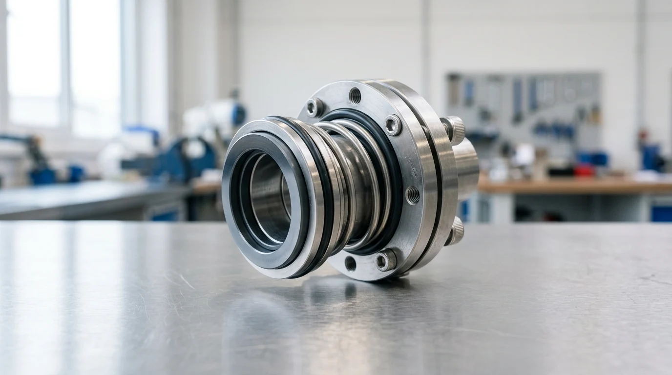
Why Mechanical Seals Matter in Oil and Gas
Mechanical seals represent one of the most critical components within oil and gas pumping systems. Their primary function is to contain process fluids at the point where a rotating shaft passes through a stationary pump casing. In an industry where fugitive emissions, volatile organic compounds (VOCs), and hazardous hydrocarbons pose severe safety and environmental risks, the integrity of the sealing mechanism is paramount. Selecting the appropriate mechanical seals requires a rigorous engineering approach that balances fluid dynamics, metallurgy, and operational safety margins.
The financial implications of seal failure extend far beyond the cost of the replacement component. Unplanned pump shutdowns can halt production lines, leading to revenue losses that frequently exceed hundreds of thousands of dollars per day in high-capacity refineries or offshore platforms. Consequently, engineering teams must evaluate mechanical seals not merely as consumable hardware, but as strategic assets essential to overall plant availability and regulatory compliance.
How Mechanical Seals Affect Pump Reliability
The reliability of centrifugal pumps in hydrocarbon processing is inextricably linked to mechanical seal performance. Industry data indicates that seal failures account for approximately 65% to 70% of all pump maintenance interventions. A well-specified seal, operating within its designed parameters, should achieve a Mean Time Between Failures (MTBF) of at least 25,000 hours (approximately three years), aligning with the baseline expectations set by API 682 standards.
Achieving this 25,000-hour threshold requires mitigating detrimental dynamic forces. Excessive shaft vibration, thermal distortion of the seal faces, and inadequate lubrication film thickness rapidly degrade seal integrity. Engineers must ensure that the pump’s radial and axial thrust loads are strictly controlled, as deflections exceeding 0.05 mm (0.002 inches) at the seal face can break the micro-fluid film, leading to dry running, catastrophic heat generation, and immediate failure.
Key Operating Risks in Upstream Applications
Upstream oil and gas environments introduce extreme operational hazards that challenge standard sealing technologies. Pumps transferring crude oil, produced water, or multiphase fluids frequently encounter high concentrations of abrasive particulates, such as frac sand or reservoir silts. These abrasives can embed in softer carbon seal faces or erode the seal hardware, necessitating hard-on-hard face pairings and robust environmental controls.
Furthermore, upstream applications often involve sour gas (hydrogen sulfide, H2S) and exceptionally high pressures. Injection pumps and pipeline boosters may operate at discharge pressures exceeding 150 bar (2,175 psi). Under these conditions, the mechanical seals must withstand massive hydraulic forces that can distort the seal rings. The presence of H2S also dictates stringent metallurgical requirements, compelling the use of NACE MR0175/ISO 15156 compliant alloys, such as Hastelloy C-276 or Duplex stainless steels, to prevent sulfide stress cracking.
Mechanical Seal Definitions and Service Conditions
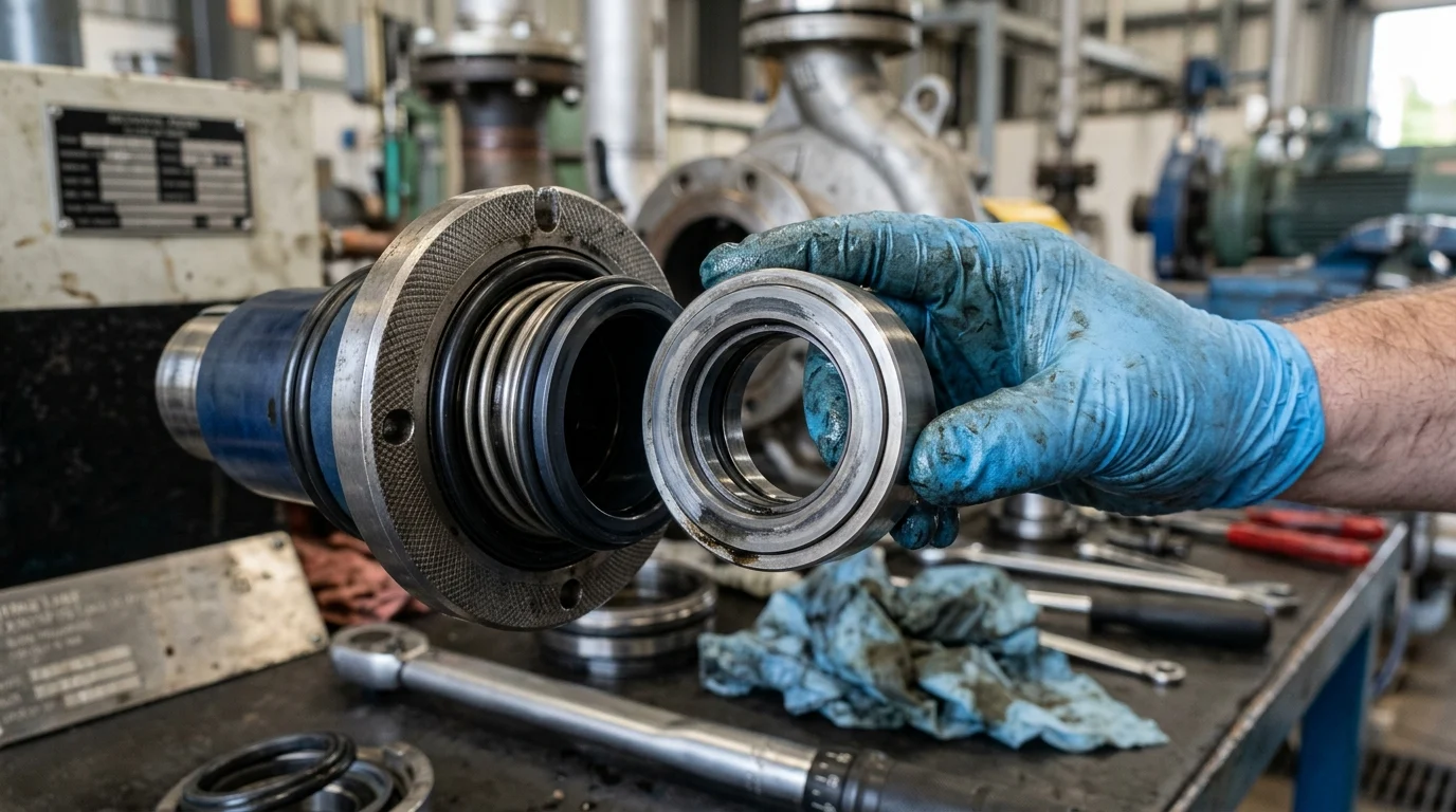
Defining the application envelope is the foundational step in mechanical seal selection. A seal is not a static plug; it is a highly engineered dynamic bearing that relies on the process fluid—or a dedicated barrier fluid—for lubrication and cooling. Accurate characterization of the service conditions ensures that the micro-gap between the rotating and stationary faces, typically measuring between 0.5 and 2.0 microns, remains stable across all operating phases.
Parameters That Define the Application Envelope
The application envelope is defined by a matrix of dynamic parameters: pressure, temperature, shaft speed, and shaft diameter. Dynamic pressure in the seal chamber determines the closing forces exerted on the seal faces. High-pressure applications, typically those exceeding 40 bar (580 psi), require balanced seal designs to prevent excessive face loading and premature wear. Conversely, vacuum conditions require seals engineered to prevent air ingress into the process.
Temperature and shaft speed further constrain the selection. Process temperatures in oil refineries can range from cryogenic levels of -100°C (-148°F) in liquefied natural gas (LNG) services to over 400°C (750°F) in bottoms residue pumps. High temperatures degrade standard elastomers, necessitating the use of perfluoroelastomers (FFKM) or flexible graphite secondary seals. Shaft speeds, often running at 3,600 RPM in standard induction motor applications, dictate the frictional heat generation at the seal faces, which must be dissipated efficiently to prevent fluid vaporization.
How to Classify Fluids, Solids, Gas Content, and Vapor
The physical and chemical properties of the pumped medium dictate the required seal design and environmental support systems. Fluids must be classified by their specific gravity, viscosity, and toxicity. Highly viscous fluids, such as heavy crude oil exceeding 500 cSt, can cause high shear resistance and require robust drive mechanisms to prevent seal component twisting or failure during cold startups.
| Fluid Category | Typical Characteristics | Primary Seal Design Impact | Typical Viscosity / Margin |
|---|---|---|---|
| Light Hydrocarbons (NGLs) | Low lubricity, highly volatile | Requires high vapor pressure margin, dual seals | < 0.5 cSt / High flash risk |
| Heavy Crude / Residuum | High viscosity, potential for coking | Requires hard faces, steam quench (Plan 62) | 100 – 10,000 cSt |
| Sour Water / Slurries | Corrosive, abrasive particulates | Hard-on-hard faces (SiC/SiC), external flush | 1 – 5 cSt / High abrasion |
| Toxic / Lethal Fluids (H2S) | High environmental/safety risk | Unpressurized or pressurized dual seals | Varies / Zero emission target |
Vapor pressure margin is a critical calculation for light hydrocarbons, such as propane or butane. The fluid in the seal chamber must be maintained at a pressure sufficiently higher than its vapor pressure at the operating temperature. If the pressure margin drops below approximately 3.5 bar (50 psi) or the temperature rises too close to the boiling point, the fluid will flash into a gas between the seal faces. This flashing eliminates lubrication, causing thermal shock and instantaneous seal failure.
Comparing Mechanical Seal Designs and Materials
The architecture of a mechanical seal and the materials used in its construction dictate its capability to survive the defined application envelope. Modern oil and gas facilities predominantly utilize cartridge-style seals, which pre-assemble the rotating elements, stationary faces, and gland plate into a single, pre-set unit. This design eliminates the need for complex field measurements, significantly reducing installation errors and improving overall reliability.
Seal Configurations for Oil and Gas Pumps
Seal configurations are broadly categorized into single and dual arrangements. Arrangement 1 utilizes a single seal and is restricted to non-hazardous, non-volatile fluids where minor leakage is environmentally acceptable. Arrangement 2 consists of an unpressurized dual seal system (a primary inner seal and a secondary outer seal) designed to capture secondary leakage of hazardous fluids, routing it to a flare or recovery system.
Arrangement 3 provides the highest level of emission control. It utilizes a pressurized dual seal configuration where a barrier fluid is maintained at a pressure higher than the pump seal chamber. Because the barrier fluid pressure is typically 1.5 to 2.0 bar (20 to 30 psi) above the process pressure, any leakage across the inner seal face flows into the pump, guaranteeing zero emissions of the process fluid to the atmosphere. This configuration is mandatory for highly toxic or lethal services.
Seal Face Materials, Elastomers, and Springs
The selection of tribological face materials and secondary sealing elastomers determines the seal’s wear rate and chemical compatibility. Silicon Carbide (SiC) is the industry standard for hard faces due to its exceptional hardness, chemical inertness, and high thermal conductivity. Tungsten Carbide (WC) is occasionally preferred for high-torque, abrasive applications due to its superior fracture toughness, though it is heavier and less chemically resistant than SiC.
| Material Pairing | Compressive Strength (MPa) | Thermal Conductivity (W/m·K) | Primary O&G Application |
|---|---|---|---|
| Carbon vs. Silicon Carbide | Low (~250) | Moderate (~120 for SiC) | Clean, non-abrasive hydrocarbons, lubricating fluids. |
| Silicon Carbide vs. SiC | High (~2,500) | High (~120) | Abrasive slurries, sour water, light hydrocarbons. |
| Tungsten Carbide vs. SiC | Very High (~4,000 for WC) | High (~100 for WC) | High-pressure injection, extreme shock loads. |
Secondary seals, typically O-rings, must be carefully matched to the process fluid and temperature. Fluoroelastomers (FKM) are common up to 200°C (390°F), but aggressive chemicals or higher temperatures necessitate Perfluoroelastomers (FFKM), which can withstand up to 320°C (600°F). For extreme high-temperature refinery services exceeding elastomer limits, engineers deploy welded metal bellows seals utilizing flexible graphite secondary seals.
Comparison Criteria for Seal Design and Barrier Fluids
Dual seals require dedicated piping plans to circulate barrier or buffer fluids, dissipate heat, and monitor performance. API Plan 52 is used for Arrangement 2 unpressurized systems, utilizing a reservoir to circulate a buffer fluid. API Plan 53 (A, B, or C) is utilized for Arrangement 3 pressurized systems. Plan 53A uses a gas-pressurized reservoir, typically limited to barrier pressures of 10 bar (150 psi) due to gas solubility issues.
For higher pressures, Plan 53B utilizes a bladder accumulator to separate the pressurizing gas from the barrier fluid, preventing gas entrainment. Plan 53C utilizes a piston accumulator that tracks the pump discharge pressure, automatically maintaining a constant differential pressure. The choice of barrier fluid—often a synthetic PAO oil or a water/glycol mixture—must prioritize high thermal stability, high flash point, and absolute compatibility with the process fluid in the event of an inner seal failure.
Standards, Compliance, and Lifecycle Requirements
Standardizing mechanical seal procurement across an oil and gas enterprise reduces inventory complexity, ensures regulatory compliance, and establishes a baseline for reliability. The industry relies heavily on established mechanical and environmental standards to govern the design, testing, and application of sealing systems, ensuring that components sourced globally meet rigorous performance criteria.
API 682, API 610, ISO, and ATEX Requirements
API Standard 682 (currently in its 4th Edition) is the definitive global standard for mechanical seals in the petroleum, natural gas, and chemical industries. API 682 categorizes seals based on the pump type and operating parameters. Category 1 seals are intended for non-API 610 pumps in moderate temperatures (-40°C to 260°C) and pressures up to 22 bar (315 psi). Category 2 and 3 seals are designed for API 610 heavy-duty process pumps, with Category 3 requiring the most stringent testing and documentation, suitable for pressures up to 40 bar (580 psi).
Beyond API 682, international safety standards dictate seal requirements in hazardous zones. The ATEX directive (specifically for equipment used in explosive atmospheres within the European Union and adopted globally) requires seals to be certified against creating ignition sources. This mandates strict limits on maximum surface temperatures and requires continuous monitoring systems, such as dual-level transmitters in seal reservoirs, to detect failures before explosive mixtures can form.
Installation and Commissioning Considerations
The most elegantly engineered mechanical seal will fail prematurely if installation tolerances are ignored. Prior to installing a cartridge seal, technicians must verify the mechanical integrity of the pump. Shaft runout must be measured using dial indicators and should not exceed 0.05 mm (0.002 inches) Total Indicator Reading (TIR). Shaft endplay (axial movement) must be restricted to less than 0.13 mm (0.005 inches).
Commissioning procedures are equally critical. The seal chamber must be properly vented to remove trapped air; running a seal dry for even 30 seconds at 3,600 RPM will generate enough thermal shock to crack silicon carbide faces. Furthermore, barrier fluid systems must be fully pressurized and circulated prior to starting the pump, ensuring the dynamic fluid film is established before rotational shear forces are applied.
Lifecycle Cost and Spare Parts Strategy
Evaluating mechanical seals solely on initial procurement cost (CAPEX) is a fundamental error in oil and gas operations. The purchase price of a mechanical seal typically represents only 15% to 20% of its Total Cost of Ownership (TCO) over a 10-year lifecycle. The remaining 80% to 85% comprises maintenance labor, barrier fluid consumption, replacement parts, and the operational penalty of pump downtime.
A robust spare parts strategy is essential for minimizing Mean Time To Repair (MTTR). Facilities should maintain a localized inventory of critical cartridge seals, particularly for unspared (single-train) pumps where failure halts production. For standardized API 682 Category 2 and 3 seals, operators frequently negotiate exchange programs with seal manufacturers, returning depleted cartridges for factory refurbishment, which generally costs 40% to 60% of the price of a new unit while restoring it to original OEM specifications.
How Buyers Should Choose the Right Mechanical Seal
Selecting the optimal mechanical seal bridges the gap between theoretical engineering and practical procurement. Buyers and reliability engineers must collaborate to navigate a complex matrix of operational requirements, capital constraints, and long-term maintenance strategies. A structured methodology prevents over-engineering, which inflates budgets, and under-engineering, which invites catastrophic failures.
Step-by-Step Selection Process for Engineering Teams
Engineering teams should adopt a standardized, step-by-step selection procedure. Step one involves completing an API 682 data sheet, which captures exact fluid properties, minimum/normal/maximum operating temperatures, and pump casing dimensions. Step two requires defining the environmental and emission constraints; if local regulations mandate VOC emissions below 500 parts per million (ppm), a dual seal arrangement is automatically triggered.
Step three involves consulting with multiple original equipment manufacturers (OEMs) to evaluate custom versus standard solutions. Engineers must scrutinize the proposed piping plans and thermal analyses provided by the vendors. For highly critical applications, such as supercritical CO2 or flashing hydrocarbons, buyers should request finite element analysis (FEA) reports demonstrating that seal face deflection remains within acceptable micrometer tolerances under maximum pressure and thermal transient conditions.
Decision Matrix for Safety, Reliability, and Cost
Procurement decisions ultimately require a balanced matrix weighing safety, reliability, and cost. Upgrading from a single seal (Arrangement 1) to a fully pressurized dual seal (Arrangement 3) with an API Plan 53B system can increase the initial capital expenditure from $3,500 to over $25,000 per pump. However, this premium is easily justified for hazardous services.
Buyers should utilize a risk-based decision framework. If a seal failure risks a localized fire, environmental fines exceeding $100,000, or a total plant shutdown costing $500,000 per day, the highest tier of seal technology and barrier support is mandatory. Conversely, for utility water or benign transfer services where leaks can be safely contained and spared pumps are available, standardizing on cost-effective, single-cartridge seals with basic flush plans provides the best return on investment without compromising facility safety.
Key Takeaways
- Treat mechanical seals as reliability-critical assets because seal failures account for roughly 65% to 70% of pump maintenance interventions.
- Specify seals from complete service data, including fluid chemistry, pressure, temperature, solids content, shaft speed, and vapor pressure.
- Aim for an MTBF of at least 25,000 hours by controlling vibration, heat generation, lubrication film stability, and shaft movement.
- Keep shaft deflection at the seal face below 0.05 mm to reduce the risk of film breakdown, dry running, and rapid seal failure.
- Use hard-on-hard face materials and proper flush or barrier systems when pumping crude, produced water, or fluids containing frac sand and silt.
- Select NACE MR0175/ISO 15156 compliant materials for sour gas service to prevent sulfide stress cracking under high-pressure conditions.
Frequently Asked Questions
Why are mechanical seals so critical in oil and gas pumps?
They contain hydrocarbons, VOCs, and hazardous fluids at the rotating shaft interface. A poor seal choice can cause leakage, emissions, safety incidents, and unplanned shutdowns that cost far more than the seal itself.
What operating data is needed before selecting a mechanical seal?
Define fluid type, pressure, temperature, shaft speed, solids content, vapor pressure, corrosiveness, and whether the service includes sour gas, abrasive media, or dry-running risk.
When should a double mechanical seal be used?
Use a double seal when the pumped fluid is toxic, flammable, volatile, abrasive, or likely to crystallize. A barrier or buffer fluid helps control emissions, improve lubrication, and protect the seal faces.
What seal face materials work best for abrasive oilfield fluids?
Hard face pairings such as silicon carbide versus silicon carbide are often preferred for fluids containing sand, silt, or other abrasive particles because they resist scoring and erosion better than softer materials.
How does API 682 influence seal selection?
API 682 provides widely used reliability and design guidance for refinery and oil and gas pump seals, including expectations such as long service life, robust materials, and suitable seal support systems.

Post time: Sep-30-2026