


Introduction
Leak prevention in rotating equipment depends not just on seal materials, but on seal design. Metal bellows mechanical seals address one of the most common failure points in conventional seals by replacing dynamic elastomers with a flexible metal bellows that maintains face loading under demanding conditions. This makes them especially valuable in high-temperature, corrosive, and emissions-sensitive services where even minor leakage can affect safety, compliance, and uptime. Understanding how these seals work helps explain why they are often chosen for stringent zero-emissions goals, and what advantages they offer over traditional pusher seal arrangements in real operating environments.
Why Metal Bellows Mechanical Seals Matter for Leakage Prevention
In modern fluid handling systems, achieving zero fugitive emissions and maximizing equipment reliability are paramount objectives for plant operators. Metal bellows mechanical seals have emerged as the definitive sealing technology for high-temperature, highly corrosive, and environmentally sensitive applications. Unlike traditional pusher seals, which rely on a dynamic secondary elastomer to accommodate face wear and shaft movement, metal bellows utilize a continuous, flexible metallic core. This fundamental architectural shift eliminates the primary vulnerability of standard seals: the dynamic O-ring.
By removing the sliding elastomer, metal bellows mechanical seals inherently prevent shaft fretting and eliminate elastomer degradation caused by extreme thermal cycling. This structural advantage allows process facilities to push operational boundaries while adhering to increasingly stringent environmental mandates, transforming a mechanical component into a critical asset for regulatory compliance and operational continuity.
Role in emissions control and reliability
The drive toward zero emissions in hydrocarbon processing and chemical manufacturing is heavily regulated by environmental agencies worldwide. Under frameworks such as the United States Environmental Protection Agency (EPA) Method 21, facilities are strictly penalized for volatile organic compound (VOC) leaks exceeding thresholds as low as 500 parts per million (ppm). In severe non-attainment zones, local air quality management districts may enforce limits down to 100 ppm.
Metal bellows mechanical seals play an indispensable role in maintaining compliance with these stringent limits. Because the bellows core is hermetically sealed via precision welding, there is no secondary dynamic leak path. This static secondary sealing arrangement ensures that fugitive emissions are kept well below regulatory thresholds, significantly improving the overall reliability and mean time between failures (MTBF) of the rotating equipment.
Where they deliver measurable value
The measurable value of metal bellows mechanical seals becomes distinctly apparent in applications where traditional elastomers fail. In refinery operations, particularly in bottom-of-the-barrel processing, heat transfer fluids, and asphalt production, pumping temperatures routinely exceed 200°C (392°F) and can peak above 400°C (752°F). At these extremes, even advanced perfluoroelastomers lose their mechanical integrity.
Furthermore, in applications prone to coking or crystallization, the absence of a sliding O-ring prevents the seal from “hanging up” on the shaft. When process fluids solidify upon atmospheric exposure, a pusher seal’s dynamic O-ring will jam, leading to immediate face separation and catastrophic leakage. The stationary secondary seal of a metal bellows design bypasses this failure mode entirely, extending pump uptime by thousands of operational hours and yielding a rapid return on investment despite a higher initial procurement cost.
How Metal Bellows Mechanical Seals Prevent Leakage
The fundamental mechanism by which metal bellows mechanical seals prevent leakage relies on their ability to maintain optimal and uniform face loading under varying dynamic conditions. The bellows unit acts simultaneously as a spring, a dynamic sealing element, and a torque transmitter. This multifunctional design streamlines the seal architecture and eliminates the internal friction that typically compromises face tracking in standard seals.
Design features that reduce leakage
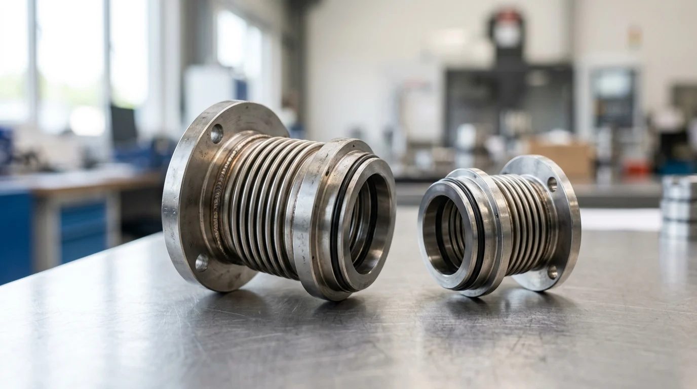
The core of the technology is the edge-welded bellows capsule. This component is constructed from a series of precision-stamped metallic diaphragms, or “leaves,” typically ranging from 0.10 to 0.15 mm in thickness. These leaves are micro-plasma or laser welded at their inner and outer diameters to form a flexible convolution.
This edge-welded design provides a 360-degree uniform spring rate, ensuring that the primary seal faces remain perfectly parallel and in constant contact, even if the pump shaft experiences minor radial deflection or axial play. The elimination of springs and dynamic O-rings removes mechanical hysteresis, meaning the seal face can respond instantaneously to shaft vibrations without the drag friction that causes leakage in conventional seals.
How operating conditions affect sealing
Operating conditions, particularly pressure and temperature, directly dictate the performance limits of the bellows. Standard single-ply metal bellows are typically rated for process pressures up to 20 to 25 bar (290 to 360 psi). For high-pressure pipeline or boiler feed applications, laminated or multi-ply bellows can be engineered to withstand pressures exceeding 60 bar (870 psi) without buckling.
Temperature variations also impact the metallurgy of the bellows core. As temperatures rise, the modulus of elasticity of the metal decreases, subtly altering the face loading. Engineering teams compensate for this by selecting high-nickel alloys and precisely calculating the compression set, ensuring the seal maintains adequate closing force whether operating at cryogenic temperatures of -75°C or extreme heat up to 425°C.
Common leakage-related failure modes
While highly robust, metal bellows mechanical seals are not immune to failure if misapplied. Torsional fatigue is a primary failure mode; if the fluid viscosity is exceptionally high or if the pump is operated dry, the friction at the seal faces can generate torque that exceeds the shear strength of the bellows welds, causing the convolutions to tear.
Another leakage-related failure mode is chloride stress corrosion cracking (CSCC). If inappropriate metallurgy, such as standard 300-series stainless steel, is used in a high-temperature saline or chloride-rich environment, microscopic cracks will propagate through the thin bellows leaves. Finally, thermal distortion of the seal faces due to inadequate cooling or flushing can warp the lapped surfaces, creating a microscopic gap that allows process fluid to escape.
Metal Bellows vs Pusher Seals
Selecting the correct mechanical seal architecture requires a rigorous comparative analysis between metal bellows and traditional pusher seals. While pusher seals dominate general-purpose water and light hydrocarbon applications due to their lower cost, metal bellows are the engineered solution for demanding process environments where elastomer limitations become operational liabilities.
Key differences in performance and limits
The defining difference between the two technologies lies in the secondary sealing mechanism. Pusher seals utilize a dynamic O-ring or V-ring that must slide along the shaft or sleeve to compensate for face wear. This sliding action inherently causes shaft fretting—a destructive wear mechanism—and is highly susceptible to jamming if the fluid crystallizes. Metal bellows utilize static secondary seals (typically graphite packing or static O-rings), eliminating fretting entirely.
| Feature | Metal Bellows Seal | Pusher Seal |
|---|---|---|
| Dynamic Secondary Element | None (Static only) | O-ring, V-ring, or Wedge |
| Shaft Fretting Risk | Zero | High |
| Maximum Temperature | > 400°C (750°F) | ~ 315°C (600°F) (Elastomer limit) |
| Hysteresis / Hang-up | Highly Resistant | Susceptible to jamming |
| Initial Capital Cost | Premium (Higher) | Standard (Lower) |
As detailed in the comparison, pusher seals are strictly limited by their elastomeric components. Even the most advanced perfluoroelastomers degrade rapidly above 315°C (600°F), whereas edge-welded bellows constructed from high-performance alloys can comfortably operate well beyond 400°C.
When to choose single, dual, cartridge, or dry gas seals
The configuration of the metal bellows seal must be tailored to the specific hazard level of the process fluid. Single bellows seals are specified for non-hazardous, high-temperature fluids like thermal oils, where minor vapor leakage does not pose an environmental or safety risk.
For toxic, flammable, or strictly regulated VOC applications, dual seal configurations are mandatory. A dual unpressurized seal (API Plan 52) provides a backup safety mechanism and captures emissions, while a dual pressurized seal (API Plan 53A/B/C) guarantees zero process emissions by maintaining a barrier fluid at a higher pressure than the process fluid. Cartridge configurations are overwhelmingly preferred across all these types, as they pre-set the delicate bellows compression at the factory, eliminating installation errors on the shop floor. Dry gas seals featuring bellows are also utilized in specialized vapor-phase applications where liquid barrier fluids are unacceptable.
Specification, Installation, and Compliance
Proper specification, meticulous installation, and adherence to international standards are critical to unlocking the full zero-emissions potential of metal bellows mechanical seals. A high-performance seal will fail prematurely if the surrounding environmental controls and piping plans are not engineered to support its specific operational envelope.
Critical application data to specify
When specifying a metal bellows seal, engineers must analyze several critical data points beyond just pressure and temperature. Fluid viscosity is paramount; metal bellows are generally rated for fluids up to 3,000 cSt. Exceeding this viscosity without proper heating can induce excessive torsional shear, snapping the bellows welds during pump startup.
The vapor pressure margin of the fluid must also be calculated to prevent flashing at the seal faces. If the fluid vaporizes between the primary faces, it causes dry running, rapid heat generation, and immediate face damage. Additionally, the specific gravity and the presence of suspended particulate matter dictate whether a rotating or stationary bellows design is required, as rotating bellows can self-clean via centrifugal force but are limited to lower speeds.
Installation and flush plan best practices
Installation success relies heavily on the implementation of appropriate API 682 flush plans. For high-temperature coking applications—a prime use case for metal bellows—API Plan 62 is frequently employed. This plan introduces a low-pressure steam quench to the atmospheric side of the seal, preventing the oxidation and solidification of process fluids that seep across the faces.
When utilizing dual pressurized configurations (Plan 53A or 53B), the barrier fluid system must be meticulously maintained. Best practices dictate that the barrier fluid pressure must be sustained at a minimum differential of 1.5 to 2.0 bar (22 to 29 psi) above the maximum stuffing box pressure. Failure to maintain this differential will result in process fluid reversing into the barrier system, contaminating the seal and compromising the zero-emissions mandate.
Relevant API, ISO, and emissions requirements
Compliance with international engineering standards ensures that metal bellows seals meet rigorous reliability metrics. The American Petroleum Institute (API) Standard 682 (4th Edition) and ISO 21049 provide the definitive frameworks for seal qualification. Under API 682, metal bellows fall primarily into Type B (rotating bellows) and Type C (stationary bellows) classifications.
For Category 2 and 3 pumps operating in critical refinery services, Type C stationary bellows are often mandated to handle higher shaft speeds and severe misalignments. Meeting these API specifications guarantees that the seal has undergone standardized qualification testing, ensuring it will uphold strict emissions requirements, such as maintaining VOC leakage below 500 ppm over an uninterrupted operational period of at least 25,000 hours.
How to Evaluate and Select the Right Seal
Evaluating and selecting the optimal metal bellows mechanical seal requires balancing thermodynamic limits, chemical compatibility, and total lifecycle costs. Reliability engineering teams must move beyond initial procurement prices to assess how specific metallurgical choices and seal architectures will impact long-term equipment uptime.
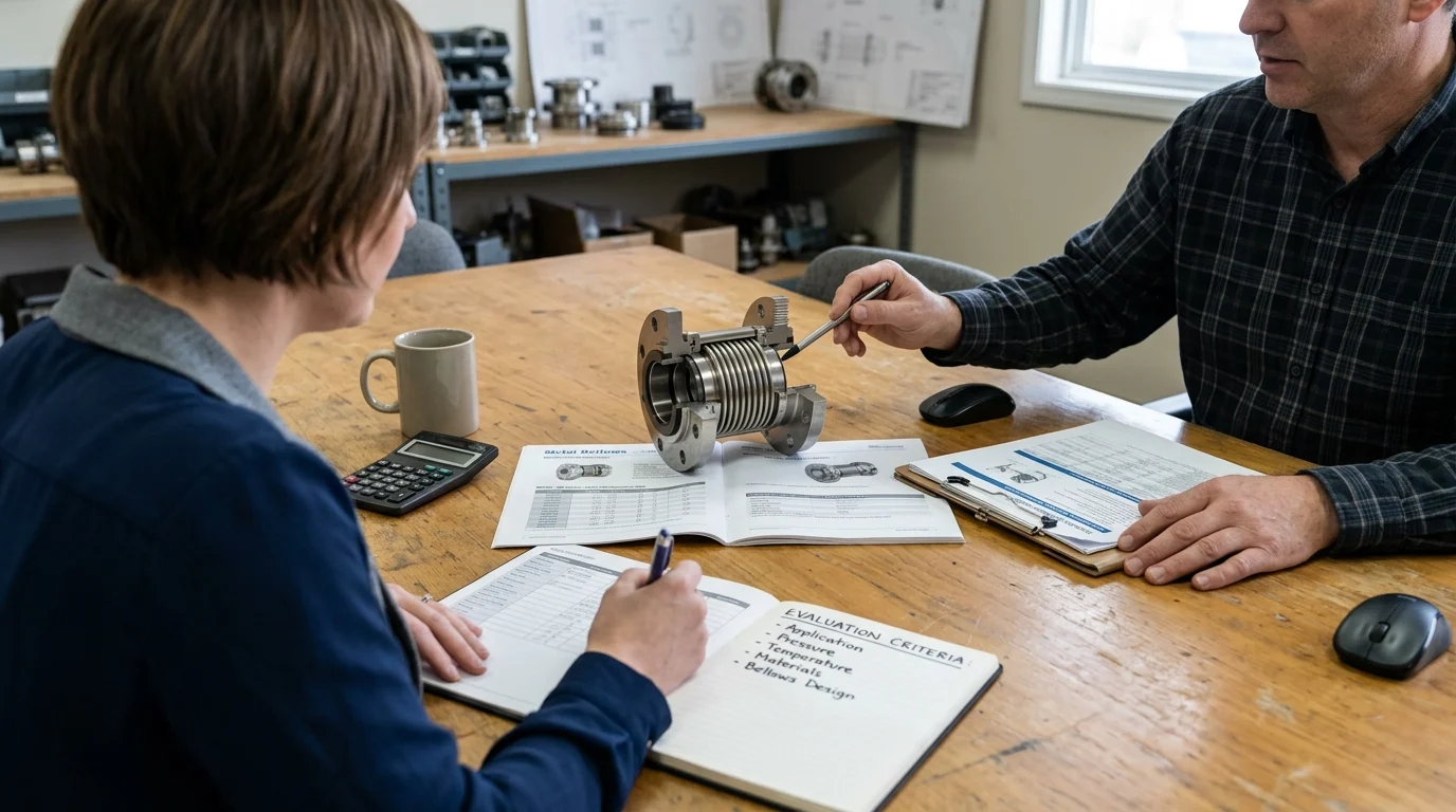
Selection criteria for end users
For end users, the selection of the bellows metallurgy is the most critical decision, as it dictates both corrosion resistance and mechanical fatigue life. Standard stainless steels are rarely sufficient for aggressive industrial applications.
| Bellows Metallurgy | Max Operating Temp | Corrosion Resistance | Typical Application |
|---|---|---|---|
| AM350 Stainless | 315°C (600°F) | Moderate | General high-temp, light oils |
| Alloy 20 (Carpenter 20) | 200°C (392°F) | High (Sulfuric Acid) | Chemical processing, acidic media |
| Inconel® 718 | 425°C (800°F) | High (General) | High-temperature refinery bottoms |
| Hastelloy® C-276 | 400°C (752°F) | Extreme (Chlorides) | Sour water, high-chloride media |
As shown in the metallurgical selection matrix, Inconel 718 is the industry standard for extreme high-temperature refinery applications, offering excellent fatigue strength. Hastelloy C-276 is specified when the process contains high concentrations of chlorides or hydrogen sulfide, which would rapidly cause stress corrosion cracking in lesser alloys.
Final guidance for maintenance and reliability teams
Maintenance and reliability teams must evaluate seal selection through the lens of Total Cost of Ownership (TCO). While a fully engineered, cartridge-style metal bellows mechanical seal carries a capital cost premium of 20% to 30% over a comparable pusher seal, the elimination of shaft sleeve replacement and the reduction in unplanned downtime rapidly offset this initial investment.
Final guidance for reliability programs involves establishing strict key performance indicators (KPIs) for rotating equipment.
Key Takeaways
- The most important conclusions and rationale for Metal Bellows Mechanical Seals
- Specs, compliance, and risk checks worth validating before you commit
- Practical next steps and caveats readers can apply immediately
Frequently Asked Questions
Why do metal bellows mechanical seals leak less than pusher seals?
They remove the dynamic O-ring, a common leak path. The welded metal bellows provides uniform face loading and a static secondary seal, reducing fretting, hang-up, and fugitive emissions.
When should I choose a metal bellows mechanical seal?
Choose it for high-temperature, corrosive, coking, or crystallizing services where elastomers fail. It is especially useful in chemical, oil and gas, power, and marine pump applications.
Can metal bellows mechanical seals support zero-emission goals?
Yes. Their hermetically welded bellows and static secondary sealing help keep VOC leakage extremely low, supporting stricter plant emission targets and compliance-focused maintenance programs.
What operating limits should buyers check before selecting one?
Verify process temperature, pressure, media corrosiveness, shaft movement, and pump model. Standard designs often suit moderate pressures, while multi-ply bellows are used for higher-pressure duties.
Does Victor Seals supply OEM-compatible metal bellows seals for industrial pumps?
Yes. Victor Seals manufactures metal bellows mechanical seals and OEM-compatible replacements for many pump maintenance needs, including brands such as Grundfos, IMO, Alfa Laval, and Allweiler.
Post time: Jun-01-2026