


Mechanical Seals are essential for a robust Pump Sealing Mechanism, effectively preventing fluid leakage around a rotating pump shaft. Understanding the Mechanical Seal Working Principle involves recognizing the Importance of O-rings in pump seals for static sealing and the Role of springs in mechanical seals for maintaining face contact. This comprehensive approach clarifies How a centrifugal pump mechanical seal works. In 2024, these vital components generated USD 2,004.26 Million in market revenue.
Key Takeaways
- Mechanical seals stop fluid leaks around a pump’s spinning shaft. They use two main parts, a rotating face and a stationary face, that press together to create a tight seal.
- A thin layer of fluid, called the hydrodynamic film, forms between these faces. This film acts like a lubricant, reducing wear and stopping leaks, which helps the seal last longer.
- Choosing the right mechanical seal depends on factors like the type of fluid, pressure, and speed. Correct selection and care help seals work well and save money on maintenance.
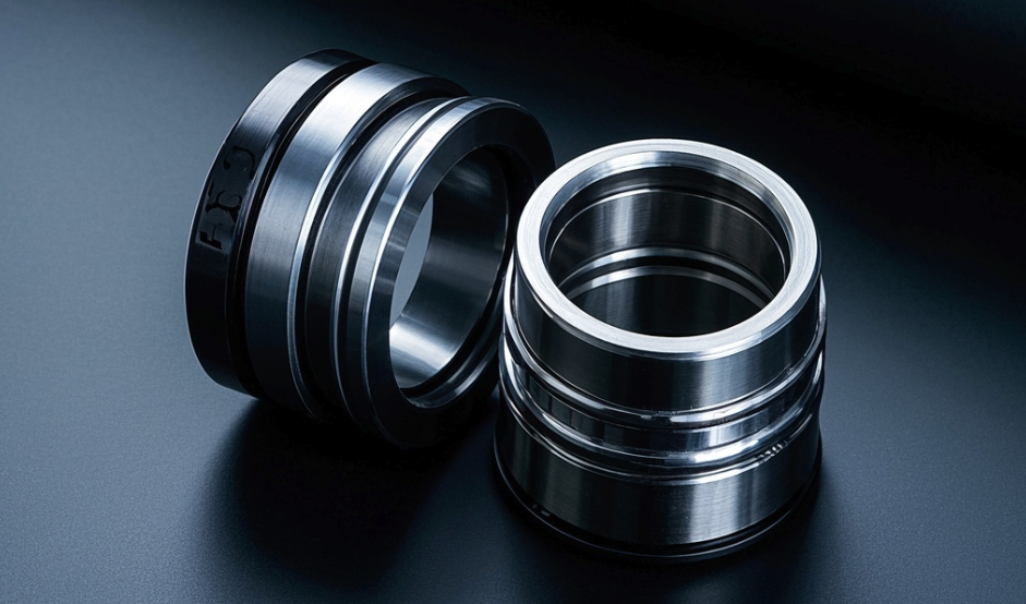
Key Components of Pump Mechanical Seals
Understanding the individual parts of a mechanical seal helps clarify its overall function. Each component plays a crucial role in preventing leakage and ensuring efficient pump operation.
Rotating Seal Face
The rotating seal face attaches directly to the pump shaft. It spins with the shaft, forming one half of the primary sealing interface. Manufacturers select materials for this component based on the fluid properties and operating conditions.
Common materials for rotating seal faces include:
- Carbon graphite blends, often used as the wearing face material.
- Tungsten carbide, a hard face material bound with cobalt or nickel.
- Ceramic, such as aluminum oxide, suitable for lower-duty applications.
- Bronze, a softer and more compliant material with limited lubricating properties.
- Ni-Resist, an austenitic cast iron containing nickel.
- Stellite®, a cobalt-chromium alloy metal.
- GFPTFE (Glass Filled PTFE).
Both surface finish and flatness are critical for rotating seal faces. Surface finish, which describes roughness, is measured in terms of ‘rms’ (root mean square) or CLA (center line average). Flatness, on the other hand, describes a level surface without elevations or depressions. Engineers often refer to flatness as waviness in mechanical seals. They typically measure flatness using an optical flat and a monochromatic light source, such as a helium gas light source. This light source produces light bands. Each helium light band represents 0.3 microns (0.0000116 inches) of deviation from flatness. The number of light bands observed indicates the degree of flatness, with fewer bands signifying greater flatness.
It requires flatness on the order of millionths of an inch per square inch to seal.
For most applications involving rotating seal faces, an ideal surface roughness is typically around 1 to 3 microinches (0.025 to 0.076 micrometers). The flatness tolerance is also very tight, often requiring precision within a few millionths of an inch. Even minor warping or unevenness can lead to leakage. The table below shows typical flatness and surface finish requirements:
| Material | Flatness (Light Bands) | Surface Finish (µm) |
|---|---|---|
| Carbon and GFT | 2 to 3 | N/A |
| TC, SiC, Ceramic | 1 to 2 | N/A |
| High Pressure (>40 bar) | Within 1 | N/A |
| Tungsten Carbide | N/A | 0.01 |
| Silicon Carbide | N/A | 0.04 |
| Hard Carbon | N/A | 0.1 |
| Ceramic | N/A | 0.07 |
Stationary Seal Face
The stationary seal face remains fixed to the pump housing. It provides the other half of the primary sealing interface. This component does not rotate. Its materials must possess high hardness and wear resistance to withstand constant contact with the rotating face.
Carbon seal faces are widely used and can be alloyed for varied frictional resistance. They are generally chemically inert. Tungsten carbide offers superior chemical, tribological, and thermal resistance compared to carbon. Silicon carbide maintains strength at high temperatures, has excellent corrosion resistance, and low thermal expansion. This makes it suitable for abrasive, corrosive, and high-pressure applications. Aluminum oxide, due to its hardness, provides excellent wear characteristics.
Here are some common materials and their properties:
- Tungsten Carbide: This material is highly resilient. It offers exceptional particulate and impact resistance, though it has lower tribological performance than Silicon Carbide. Its Mohs Hardness is 9.
- Carbon: Most effective when paired with a harder material, carbon is commercially attractive. However, it is soft and brittle, making it unsuitable for media with solid particulates. Triple Phenolic Resin Impregnated Carbon Graphite offers higher wear performance for demanding applications with marginal lubrication or aggressive chemicals.
- Alumina Ceramic (99.5% purity): This is an economical option with exceptional chemical and wear resistance due to high hardness. Its Mohs Hardness is 9-10. However, it is prone to physical and thermal shock fracture. This makes it unsuitable for media with solid particulates, low lubrication, or sudden temperature changes.
- Silicon Carbide: This material is considered the most tribologically effective when paired with carbon. It is the hardest and most wear-resistant seal face material, offering exceptional chemical capability. For lubricating media with high solid particulates, pairing two Silicon Carbide seal faces is recommended. Its Mohs Hardness is 9-10.
Secondary Sealing Elements
Secondary sealing elements provide static sealing between the seal components and the pump housing or shaft. They also allow for axial movement of the seal faces. These elements ensure a tight seal even when the primary faces move slightly.
Different types of secondary sealing elements include:
- O-rings: These have a circular cross-section. They are simple to install, versatile, and the most common type. O-rings are available in various elastomeric compounds and durometers for different temperature and chemical compatibility needs.
- Elastomer or thermoplastic bellows: These are used where sliding dynamic seals are not optimal. They deflect to allow motion without sliding and come in various materials. People also know them as ‘boots’.
- Wedges (PTFE or carbon/graphite): Named for their cross-sectional shape, wedges are used when O-rings are unsuitable due to temperature or chemical exposure. They require external energization but can be cost-effective. Limitations include potential for ‘hang-up’ in dirty services and fretting.
- Metal bellows: These are employed in high-temperature, vacuum, or hygienic applications. They are formed from a single piece of metal or welded. They provide both secondary sealing and spring load for axial movement.
- Flat gaskets: These are used for static sealing, such as sealing the mechanical seal’s gland to the mounting flange or other static interfaces within the assembly. They have no ability to move and are compression-type seals, typically for single use.
- U-cups and V-rings: Named for their cross-sections, these are made from elastomeric or thermoplastic materials. They are applied in low-temperature, higher-pressure applications, and where specific chemical compatibility is required.
Material compatibility for secondary sealing elements is crucial. Aggressive fluids can react with seal materials, breaking down their molecular structure. This leads to weakening, brittleness, or softening. This can cause thinning, pitting, or complete disintegration of seal components, including secondary sealing elements. For highly corrosive fluids like hydrofluoric (HF) acid, perfluoroelastomers are recommended as the secondary sealing element. This is due to the need for chemically-resistant materials that can withstand the volatility and pressure of such aggressive chemicals. Chemical incompatibility leads to material degradation and corrosion in Mechanical Seals, including secondary sealing elements. This can cause seal components to swell, shrink, crack, or corrode. Such damage compromises the seal’s integrity and mechanical properties, resulting in leakage and a shorter service life. High temperatures, or exothermic reactions caused by incompatible fluids, can also damage seal materials by exceeding their critical temperature limits. This leads to a loss of strength and integrity. Key chemical properties defining compatibility include the fluid’s operating temperature, pH level, system pressure, and chemical concentration. These factors determine a material’s resistance to degradation.
Spring Mechanisms
Spring mechanisms apply a constant and uniform force to keep the rotating and stationary seal faces in contact. This ensures a tight seal even as the faces wear or as pressure fluctuates.
Different types of spring mechanisms include:
- Conical Spring: This spring is cone-shaped. It is often used in slurry or dirty media due to its open design, which prevents particle accumulation. It provides uniform pressure and smooth movement.
- Single Coil Spring: This is a simple helical spring. It is primarily used in pusher-type seals for clean liquids like water or oil. It is easy to assemble, low-cost, and delivers consistent sealing force.
- Wave Spring: This spring is flat and wavy. It is ideal for compact seals where axial space is limited. It ensures equal pressure in small spaces, reduces overall seal length, and promotes stable face contact. This leads to low friction and longer seal life.
- Multiple Coil Springs: These consist of many small springs arranged around the seal face. They are commonly found in balanced mechanical seals and high-speed pumps. They apply even pressure from all sides, reduce face wear, and operate smoothly at high pressures or RPMs. They offer reliability even if one spring fails.
Other forms of spring mechanisms also exist, such as leaf springs, metal bellows, and elastomeric bellows.
Gland Plate Assembly
The gland plate assembly serves as the mounting point for the mechanical seal to the pump housing. It holds the stationary seal face securely in place. This assembly ensures proper alignment of the seal components within the pump.
The Working Principle of Mechanical Seals
Creating the Sealing Barrier
Mechanical seals prevent fluid leakage by establishing a dynamic seal between a rotating shaft and a stationary housing. Two precisely engineered faces, one rotating with the shaft and the other fixed to the pump casing, form the primary sealing barrier. These faces press against each other, creating a very narrow gap. For gas seals, this gap typically measures 2 to 4 micrometers (µm). This distance can change based on pressure, application speed, and the type of gas sealed. In mechanical seals operating with aqueous fluids, the gap between seal faces can be as small as 0.3 micrometers (µm). This extremely small separation is crucial for effective sealing. The fluid film thickness between seal faces can range from a few micrometers to several hundred micrometers, influenced by various operational factors. A micrometer is one-millionth of a meter or 0.001mm.
The Hydrodynamic Film
A thin layer of fluid, known as the hydrodynamic film, forms between the rotating and stationary seal faces. This film is essential for the seal’s operation and longevity. It acts as a lubricant, significantly reducing friction and wear between the seal faces. The film also functions as a barrier, preventing fluid leakage. This hydrodynamic film achieves maximum hydrodynamic load support, which extends mechanical face seal life by significantly reducing wear. Circumferentially varying waviness on one face can cause hydrodynamic lubrication.
The hydrodynamic film offers greater film stiffness and results in lower leakage compared to many hydrostatic designs. It also exhibits lower lift-off (or spin-up) speeds. Grooves actively pump fluid into the interface, building hydrodynamic pressure. This pressure supports the load and reduces direct contact. Diffuser grooves can achieve higher opening force for the same leakage compared to flat cross-section spiral grooves.
Different lubrication regimes describe the film’s behavior:
| Regime | Film Thickness / Contact | Friction & Wear | Leakage |
|---|---|---|---|
| Full Film Lubrication | Sufficiently thick film, no stator-rotor contact | Significantly reduced | Could be excessive |
| Boundary Lubrication | Partly discontinuous film, solid contacts in some areas | Can obviously reduce | N/A |
| Mixed Lubrication | Part of load by mechanical contact, majority by fluid pressure | Relatively moderate | Very low |
Fluid viscosity plays a critical role in the formation and stability of this film. A study on thin, viscous, Newtonian liquid films showed that odd viscosity introduces new terms into the pressure gradient of the flow. This significantly modifies the nonlinear evolution equation for film thickness. Linear analysis demonstrates that odd viscosity consistently exerts a stabilizing effect on the flow field. The motion of a vertical plate also influences stability; down-moving motion enhances stability, while up-moving motion reduces it. Numerical solutions further illustrate the role of odd viscosity in thin film flows under various plate motions in isothermal environments, clearly showing its influence on flow stability.
Forces Influencing Mechanical Seals
Several forces act on the seal faces during pump operation, ensuring they remain in contact and maintain the sealing barrier. These forces include mechanical force and hydraulic force. Mechanical force applies from springs, bellows, or other mechanical elements. It maintains contact between the seal faces. Hydraulic force generates from the process fluid pressure. This force pushes the seal faces together, enhancing the sealing effect. The combination of these forces creates a balanced system that allows the seal to operate effectively.
Lubrication and Heat Management for Mechanical Seals
Proper lubrication and effective heat management are vital for the reliable operation and longevity of mechanical seals. The hydrodynamic film provides lubrication, minimizing friction and wear. However, friction still generates heat at the sealing interface. For industrial seals, typical heat flux rates range from 10-100 kW/m². For high-performance applications, heat flux rates can be as high as 1000 kW/m².
Friction-based heat generation is the primary source. It occurs at the sealing interface. The heat generation rate (Q) calculates as μ × N × V × A (where μ is the friction coefficient, N is the normal force, V is the velocity, and A is the contact area). The generated heat distributes between the rotating and stationary faces based on their thermal properties. Viscous shear heating also generates heat. This mechanism involves shear stress in thin fluid films. It calculates as Q = τ × γ × V (shear stress × shear rate × volume) and becomes particularly significant in high-viscosity fluids or high-speed applications.
Optimized balance ratios are a crucial design consideration to minimize heat generation as shaft speed increases. An experimental study on mechanical face seals demonstrated that the combination of balance ratio and steam pressure significantly influences wear rates and friction losses. Specifically, under conditions of a higher balance ratio, the frictional torque between the seal faces was directly proportional to the steam pressure. The study also found that a substantial reduction in frictional torques and wear rates can be achieved with low balance ratios.
Types and Selection of Mechanical Seals
Common Types of Mechanical Seals
Mechanical seals come in various designs, each suited for specific applications. Pusher seals use elastomer O-rings that move along the shaft to maintain contact. In contrast, non-pusher seals employ elastomer or metal bellows, which deform rather than move. This design makes non-pusher seals ideal for abrasive or hot fluids, as well as corrosive or high-temperature environments, often exhibiting lower wear rates.
| Feature | Pusher Seal | Non-Pusher Seal |
|---|---|---|
| Secondary Seal Type | Dynamic O-ring | Bellows (metal or elastomeric) |
| Best For | High-pressure environments | Abrasive or hot fluids, corrosive/high temp |
| Wear Rate | Moderate | Low |
Another distinction lies between cartridge seals and component seals. A cartridge mechanical seal is a pre-assembled unit, containing all seal components within a single housing. This design simplifies installation and reduces the risk of errors. Component seals, however, consist of individual elements assembled in the field, which can lead to more complex installation and a higher risk of errors. While cartridge seals have a higher upfront cost, they often lead to lower maintenance and reduced downtime.
| Feature | Cartridge Seal | Component Seal |
|---|---|---|
| Installation | Easy, pre-assembled unit | Complex, individual elements assembled in field |
| Cost | Higher upfront | Lower upfront |
| Errors | Reduced installation errors | Higher risk of installation errors |
| Maintenance | Lower, shortens downtime | Higher, requires skilled technicians |
Seals also classify as balanced or unbalanced. Balanced mechanical seals handle higher pressure differentials and maintain stable seal face positions, making them suitable for critical applications and high-speed equipment. They offer improved energy efficiency and prolonged equipment life. Unbalanced seals feature a simpler design and are more affordable. They are a practical choice for less demanding applications like water pumps and HVAC systems, where reliability is important but high pressures are not a concern.
Factors for Selecting Mechanical Seals
Selecting the correct mechanical seal requires careful consideration of several key factors. The application itself dictates many choices, including equipment setup and operating procedures. For instance, continuous operation ANSI process pumps differ significantly from intermittent service sump pumps, even with the same liquid.
Media refers to the fluid in contact with the seal. Engineers must critically evaluate the fluid’s constituents and nature. They ask if the pumped stream contains solids or corrosive contaminants like H2S or chlorides. They also consider the product’s concentration if it is a solution, and if it solidifies under any encountered conditions. For hazardous products or those lacking suitable lubrication, external flushes or double pressurized seals are often necessary.
Pressure and speed are two fundamental operating parameters. Pressure within the seal chamber must not exceed the seal’s static pressure limit. It also influences the dynamic limit (PV) based on seal materials and fluid properties. Speed significantly impacts seal performance, especially at extremes. High velocities lead to centrifugal forces on springs, favoring stationary spring designs.
Fluid characteristics, operating temperature, and pressure directly influence seal selection. Abrasive fluids cause wear on seal faces, while corrosive fluids damage seal materials. High temperatures cause materials to expand, potentially leading to leakage. Low temperatures make materials brittle. High pressures place additional stress on seal faces, necessitating a robust seal design.
Applications of Mechanical Seals
Mechanical seals find widespread use across various industries due to their critical role in preventing leakage and ensuring operational efficiency.
In oil and gas extraction, seals are vital in pumps operating under extreme conditions. They prevent hydrocarbon leaks, ensuring safety and environmental compliance. Specialized seals in subsea pumps withstand high pressure and corrosive seawater, reducing environmental risk and downtime.
Chemical processing and storage rely on seals to prevent leaks of aggressive, corrosive substances. These leaks could cause safety hazards or product loss. Advanced seals made with corrosion-resistant materials like ceramic or carbon are common in reactors and storage tanks. They extend equipment lifespan and maintain product purity.
Water and wastewater treatment facilities use seals in pumps and mixers to contain water and chemicals. These seals are designed for continuous operation and resistance to biofouling. In desalination plants, seals must endure high pressures and saline conditions, prioritizing durability for operational reliability and environmental compliance.
Abrasive slurries and corrosive fluids pose specific challenges. Abrasive particles accelerate wear on sealing surfaces. Chemical reactivity of certain fluids degrades seal materials. Solutions include advanced elastomers and thermoplastics with superior chemical resistance. They also include protective features like barrier fluid systems or environmental controls.
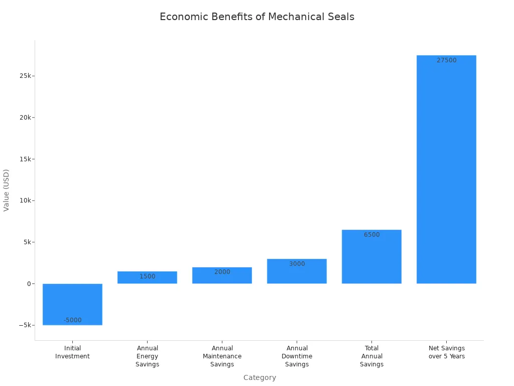
Mechanical Seals prevent leakage by forming a dynamic barrier between rotating and stationary faces. They offer significant maintenance cost savings and extend equipment life. Proper selection and maintenance ensure their longevity, often exceeding three years, providing reliable pump operation.
FAQ
What is the primary function of a mechanical seal?
Mechanical seals prevent fluid leakage around a pump’s rotating shaft. They create a dynamic barrier, ensuring efficient and safe pump operation.
What are the main parts of a mechanical seal?
The main parts include rotating and stationary seal faces, secondary sealing elements, spring mechanisms, and the gland plate assembly. Each component performs a crucial task.
Why does the hydrodynamic film matter in mechanical seals?
The hydrodynamic film lubricates the seal faces, which reduces friction and wear. It also acts as a barrier, preventing fluid leakage and extending the seal’s lifespan.
Post time: Apr-01-2026